
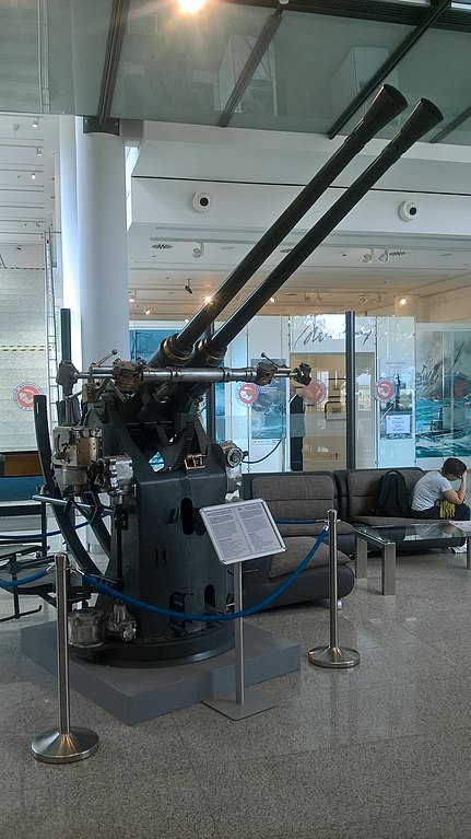
Probably the best automatic cannon anti-aircraft weapon of World War II, Bofors guns of this type remained in service long after the war ended. This weapon was used on almost every major USA and UK warship of World War II and was a very potent AA gun.
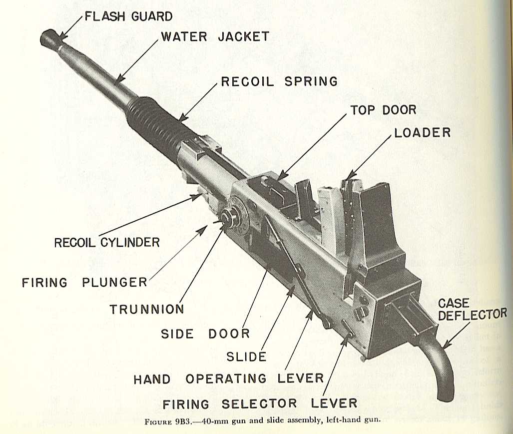
These guns are recoil operated and use a monobloc barrel with a detachable breech ring, breech
casing and automatic loader. The barrel was attached to the breech ring via an interrupted screw design.
The breech block was a vertical sliding type which was developed from the Finspong (Swedish arms
manufacturer of the 1800s) 57mm Ssk M/89B. Although often listed as being 60 calibers long, all
guns from all nations except Japan were actually 56.25 calibers in length.
This weapon traces its roots back to a 1918 Krupp design - the Bofors Company was partly
owned by German interests until 1930 - but the finished product was entirely a Bofors design
owing little or nothing to Krupp influence. During the late 1920s the Swedish Royal Navy
approached Bofors a few times with requests to design a new 40 mm AA gun to replace the
British 2-pdr. guns currently in service. Bofors showed
little interest in this project as the size of any order from the Swedish Navy
would be small and they did not see much possibility in foreign orders. However,
the Navy persisted and finally offered to help fund the development costs. With this money
in hand, Bofors started to actively work on a new AA weapon. The first
Bofors test-bed prototype was finished late in the summer of 1930 and this fired three
rounds using the automatic loader on 17 October 1930. Design and manufacturing of the first gun
followed and single shots with it were fired on 10 November 1931. By 25 November
1931 trials had progressed to firing eight rounds in 7.58 seconds. This showed that
the autoloader design concept would work, but more effort was needed before the prototype
could meet the Navy's 130 rpm requirement. After the necessary improvements, official trials
for the Swedish Navy took place successfully on 21 March 1932.
The basic design was further refined over the next two years, with 30,000 hours
of drawing board work needed to produce 1,800 working drawings and 1,600 machine tool
drawings that made up the improved 40 mm L/60 Model 1934. This model was exported to
several countries but not adopted by the Swedish armed forces. What the Swedish Navy did
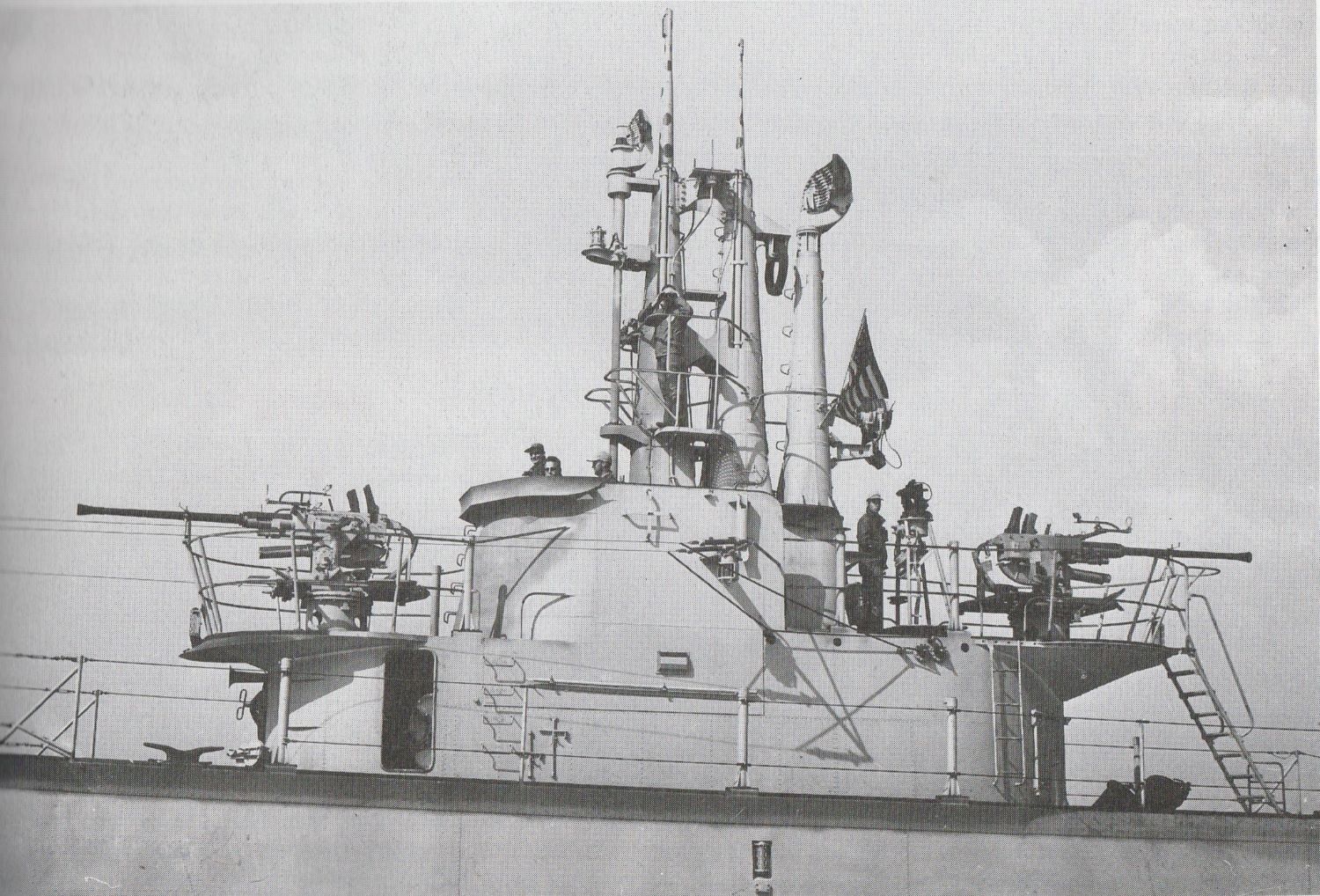
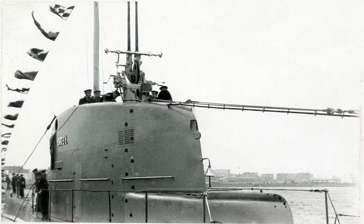
order in 1934 was a short-barrel version for submarines that was to be stowed in a waterproof
tubular container located in the conning tower or under the decking. This weapon was designated
as as the 40 mm L/43 Model 1932, please see that
datapage for details.
It was not until 1936 that the Swedish Army and Navy placed orders for a very slightly
modified version and this became the 40 mm L/60 Model 1936 whose basic design was
used for most guns produced during World War II by Bofors, the UK and the USA. Although the
UK and USA halted production with the end of the war, Bofors continued to manufacture the
40 mm L/60 until 1954 when production was halted in order to concentrate on the more powerful
40 mm L/70 and 57 mm L/60
guns.
The British Army first showed interest
in these guns in 1933 and placed an order for 100 of them in 1937.
First Royal Navy shipboard use of air-cooled guns was in late 1941 aboard
the battleships Prince of Wales and Nelson and on the cruisers Manchester
and Erebus, although some ships had earlier been temporarily armed with
Army air-cooled guns that had been "rescued" during the evacuation of the
Norway invasion forces in 1940. The British water-cooled version
was developed by copying the Dutch Hazemeyer mounting which had arrived
in Britain in 1940 aboard the Dutch minelayer Willem van der Zaan.
The first issue of locally produced water-cooled Bofors guns was to the
Black Swan class sloop HMS Whimbrel in November 1942.
The total number of air-cooled guns
built by Australia, Britain and Canada is not accurately known but was
somewhere between 2,100 and 2,800 plus about 200 to 400 guns supplied from
the United States. Water-cooled guns are better documented with 442
Mark IV and 342 Mark XI in service at the end of the war plus 786 water-cooled
guns supplied by the USA. These USA weapons had been sent to Britain
as a part of Lend-Lease or else were installed on ships refitted in USA
shipyards.
The US Army was also interested in this weapon and tested a single air-cooled
model in 1937. In 1940 the Chrysler Corporation agreed to begin manufacturing
air-cooled guns utilizing British blueprints. The USN acquired many of these
air-cooled guns during the war, although the quantity used was far less than
that of the water-cooled guns.
The US Navy had a good deal of pre-war interest in this weapon and BuOrd
purchased a sample of an water-cooled twin version from Bofors in early 1940.
Bofors instead sent an air-cooled version and this arrived in New York from
Sweden on 28 August 1940. During the same month, the Dutch escort vessel
van Kinsbergen demonstrated these weapons and their Hazemeyer control
system to USN observers in a test off Trinidad. The observers were not impressed
by the control system, but were favorably impressed by the guns themselves.
BuOrd formally obtained Swedish licenses in June 1941, although some manufacturing
had actually started prior to that time. Terms of the license included a $500,000
payment for the manufacturing rights plus $100,000 for two Bofors engineers to
help set up production. The two engineers were never sent, so as a result this
$100,000 was not paid. Bofors delivered a complete set of metric drawings as part
of their end of this contract.
It should be noted that the US Army and Navy considered the original Bofors Model
1936 design to be completely unsuitable for the mass production techniques required
for the vast number of guns needed to equip the anti-aircraft batteries and ships
of the US military. First, the Swedish guns were designed using metric measurement
units, a system all but unknown in the USA at that time. Worse still, the dimensioning
on the Swedish drawings often did not match the actual measurements taken of the
weapons. Secondly, the Swedish guns required a great deal of hand work in order to
make the finished weapon. For example, Swedish blueprints had many notes on them such
as "file to fit at assembly" and "drill to fit at assembly," all of which took much
production time in order to implement - there is a story that one USA production
engineer remarked that the Bofors gun had been designed so as to eliminate the
unemployment problems of the Great Depression. Third, the Swedish mountings were
manually worked, while the USN required power-worked mountings in order to attain the
fast elevation and training speeds necessary to engage modern aircraft. Fourth, the
Swedish twin gun mounting supplied to the USA for evaluation was air-cooled, limiting
its ability to fire long bursts, a necessity for most naval AA engagements. Finally,
the USN rejected the Swedish ammunition design as it was not boresafe, the fuze was
found to be too sensitive for normal shipboard use and its overall design was
determined to be unsuitable for mass production.
US manufacturers made radical changes to the Swedish design in order to minimize
these problems and as a result the guns and mountings produced in the USA bore little
resemblance to their Swedish ancestors. For example, all but the earliest US guns were
built to English measurement units rather than to metric units. To give one additional
example of the design differences made for USA produced weapons; the Chrysler Corporation
redesigned ten components to suit mass production techniques and this was claimed to have
saved some 7,500,000 pounds (3,402,000 kg) of material and 1,896,750 man hours during a
year's production, as well as freeing up 30 machine tools for the production of other
components.
One firm rule adopted early in the redesign process was that any new Allied
munition for these weapons needed to be completely interchangeable with existing
designs. This allowed ammunition produced by any American or British ordnance
manufacturer to be used with any weapon produced by either country, thus greatly
simplifying the logistics problems of a world-wide war. In accordance with this rule,
the USA originally adopted the British fuze design with the understanding that both
the US Army and Navy "would be free to substitute components of proven reliability
which would speed production." The fuze designed and produced in Britain was adopted
as an interim measure by the USA, but this was considered to be of an unsafe design
and unsuitable for mass production techniques. Fortunately, this fuze was almost
immediately replaced by one designed by R.L. Graumann of the Naval Ordnance Laboratory.
This fuze was simple in design and "ideally suited to mass production." Designated as
the Mark 27, this new fuze was found to be 99.9 percent efficient in ballistic
acceptance tests, a record not equaled by any other fuze of the time. Both the US Army
and the British adopted this fuze for their own production lines. The USN estimated
that the adoption of the Mark 27 saved some $250,000,000 during the war. Overall, the
USA spent over $700,000,000 on 40 mm ammunition.
The first USN pilot twin was completed in January 1942 and the first quad in April
1942. The first shipboard quad installation was on the gunnery-training ship (ex-battleship)
USS Wyoming (AG-17) on 22 June 1942, and the first twin installation was on the destroyer
USS Coghlan (DD-606) on 1 July 1942. The USA started a massive production program for these
weapons and a monthly production rate of 1,600 Army guns and 135 Navy twin-barrel guns was
achieved by December 1942. Production continued to ramp up in the following year, so much
so that the Army found that they had more guns than they could field and production of
air-cooled single guns fell from a peak of 13,485 in 1943 to 1,500 guns in 1944 and then
halted with no guns for the Army being produced during the last year of the war.
However, the needs of equipping Navy ships were not fully met until well into
1944. By that time, the pre-war 1.1" gun
had been almost totally replaced by Bofors guns. During 1944, 6,644 single
mountings and approximately 3,650 twin and 750 quad mountings were produced
with production still ramping up with at least 796 single, 3,020 twin and 800 quad
mountings being manufactured in 1945 until the end of the war halted production. To
illustrate how many of these weapons were required by the USN, note that out of the
more than 400 destroyers built for the USN between 1934 and 1946, only the four
destroyers of the pre-war Gridley class (DD-380) and those destroyers sunk early in
the war did not receive at least some Bofors guns.
Part of this increasing demand was the late war program of replacing
20 mm Oerlikon guns with the Bofors 40 mm guns,
as the smaller weapon was found to be ineffective against Japanese Kamikazes. However,
by early 1945, even the Bofors was determined to be inadequate against suicide attacks.
As a result, a crash program was started late in the war to develop a new
rapid fire 3"/50 (7.62 cm) gun to replace the
Bofors. It should be noted here that although the Bofors gun was probably the best
anti-aircraft automatic cannon of World War II, the USN considered it to be a front-line
weapon for only six years. It did remain in service in the USN until the 1970s on auxiliary
and non-modernized ships, primarily because the 3"/50 RF (7.62 cm) replacement program was
never fully funded. As late as 1977, the US Navy still had twenty-four Mark 3 Mod 0
air-cooled single guns and carriages on the active fleet list. In 1969, air-cooled Bofors
guns provided from Naval depots were used to arm Air Force AC-130 "Spectre" gunships for use
in Vietnam.
As the USN decommissioned and transferred ships to other nations following the end of World
War II, ex-US Bofors guns saw service under many flags with some still in active use as late as
2013.
Early versions of the Bofors twin mounting used friction-coupled drives, which quickly wore
out on naval ships due to salt contamination. Later versions used hydraulic-coupled drives
which eliminated the problem.
The development of the Mark 51 director system gave the USA weapons greatly improved
accuracy. For example, half of all Japanese aircraft shot down between 1 October 1944 and 1
February 1945 were credited to the Bofors/Mark 51 combination. See the essay on the
Mark 51 director on the
History and Technology section for
additional information.
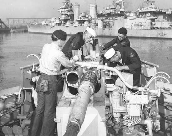
The USN 40 mm/56.3 Mark 1 and 40 mm/56.3 Mark 2 Bofors guns were both water-cooled
and were used for all twin and quad mountings. The Mark 1 was a left-hand weapon while the Mark 2
was a right-hand weapon. Except for the barrel assemblies, the components were not interchangeable.
These weapons could be fired in single-shot or automatic mode via a selector switch on the side of
the slide.
The 40 mm/56.3 M1 was an air-cooled version originally produced for the US Army. The barrel
assemblies for the M1 were interchangeable with those of British and Canadian produced air-cooled
weapons. All USN single mountings used a modified version of the Army M1 gun.
German forces captured many Bofors guns during 1939 - 1941 and most of these were either
sold back to Sweden in exchange for raw materials or placed into storage. However, after the
defeat of France in 1940, Germany had so many captured guns that it was decided to adopt
them into the armed forces and they were then designated as the 4 cm/56 Flak 28.
Earlier in 1940, the German invasion of Norway had halted production at the Waffenfabrik
Kongsberg facility just as their first four Bofors guns were nearing completion.
Waffenfabrik Kongsberg had obtained a license from Bofors in July 1937 but took years to
set up a production line. The production line sat idle for a few months following the surrender
but then restarted under German control. Repair of damaged captured guns and production of new
ammunition was also started at this facility. Most of the new guns were sent to the Kriegsmarine
where they were used on the cruisers Admiral Hipper and Prinz Eugen and on
Schnellbootes. From 1941 onwards the Hungarian firm of MAVAG, which had also obtained a
pre-war license from Bofors, produced Bofors guns for Germany as well as their own armed forces.
By July 1941 the Kriegsmarine had 247 guns in service and by March 1942 the Luftwaffe had 615 guns
in service.
Besides purchasing weapons directly from
Bofors, governments and manufacturing firms in Austria, Belgium, Czechoslovakia, Denmark, Finland,
France, Greece, Hungary, The Netherlands, Norway, Poland, Portugal and the United Kingdom all obtained
manufacturing licenses during the 1930s, but not all of these countries had started actual production
before the start of World War II. Some nations started producing guns after 1939, but Czechoslovakia,
Denmark, France, Portugal and Greece never did. Japan developed her own derivative of the Bofors gun
from captured British weapons, as detailed below.
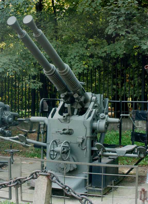
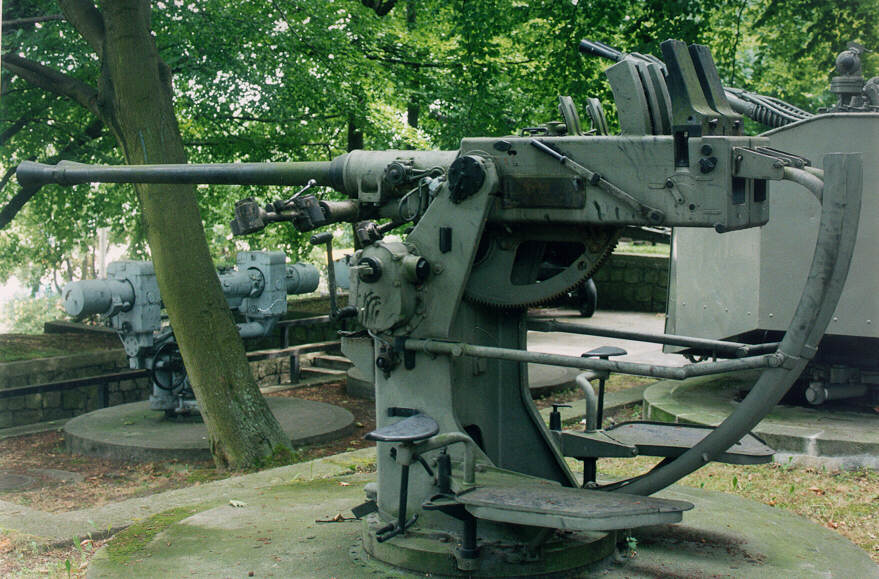
Poland was one of the first to start manufacturing and actually exported 168 guns to the United Kingdom,
France, Romania and The Netherlands. Some of those intended for the United Kingdom and The Netherlands were
stranded in Sweden when that country invoked their neutrality laws in January 1939, even though war was not
declared until September. These were eventually taken over by the Swedish armed forces. Poland also supplied
24 guns and 50,000 rounds of ammunition in 1938 to the Spanish Republicans which were eventually captured
by the Nationalists and were used as coastal defense with fourteen still in service as late as 1958.
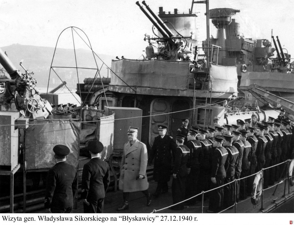
A Note on Sources: "The Bofors Gun" by Gander says that L/43 guns were sent to Poland and used on the Polish
destroyer Blyskawica and other ships but a long Email discussion and examination of Polish pre-war
photographs supplied by Maciej Tomaszewski has convinced me that Blyskawica was actually armed with
L/60 guns. At this time, he has not found any evidence that any of the Bofors guns sent to Poland were L/43 type. Additional information on guns produced and used by many nations may be found in the
Mount / Turret Data section at the bottom of this page.
| Designation | Sweden: Bofors 40 mm/60 (1.57") Model 1936
Germany: 4 cm/56 (1.57") Flak 28 Japan: 4 cm/60 (1.57") Type 5 (Model 1945) Official Designation: 60 caliber Type 5 4 cm Gun UK 1: 40 mm/56.3 (1.57") OQF Marks I, III, IV, VIII, IX, X, XI, NI and NI/I USA: 40 mm/56.3 (1.57") Mark 1, Mark 2 and M1 |
|---|---|
| Ship Class Used On | Sweden - N/A
Germany - Cruisers and S-Boats Japan - Not in service UK - Almost all major UK warships of World War II USA - Almost all major USA warships of World War II |
| Date Of Design | Bofors: 1934
Germany: N/A Japan: 1943 UK: 1941 USA: 1941 |
| Date In Service | Sweden: 1936
Germany: 1944 Japan: Not in service UK: 1941 (Bofors-produced guns) UK: 1942 (UK-produced guns) USA: 1942 |
| Gun Weight | Bofors: N/A
Germany: N/A Japan: 1,018 lbs. (462 kg) [air-cooled] UK: 1,120 to 1,163 lbs. (508 to 528 kg) [depending upon Mark] [water-cooled] USA Mark 1 and Mark 2: about 1,150 lbs. (522 kg) [water-cooled] USA M1: 1,036.5 lbs. (470 kg) [air-cooled] |
| Gun Length oa | Bofors: N/A
Germany: N/A Japan: N/A UK: 145.3 to 145.5 in (3.691 to 3.696 m) [depending upon Mark] USA: 148.8 in (3.780 m) |
| Bore Length 2 | Bofors: 88.578 in (2.250 m)
Germany: 88.578 in (2.250 m) Japan 3: 94.5 in (2.400 m) UK: 88.578 in (2.250 m) USA: 88.6 in (2.250 m) |
| Rifling Length | Bofors: 76.1 in (1.933 m)
Germany: 76.1 in (1.932 m) Japan: 78.8 in (2.000 m) UK: 75.85 in (1.927 m) USA: 75.85 in (1.927 m) |
| Grooves | Bofors: (16) 0.0236 in deep x 0.220 (0.60 x 5.59 mm)
Germany 4: (16) 0.0236 in deep x 0.220 (0.60 x 5.59 mm) Japan: (16) 0.0098 in deep (0.25 mm) UK: (16) 0.0236 in deep x 0.220 (0.60 x 5.59 mm) USA Mark 1 and Mark 2: (16) 0.0236 in deep x 0.220 (0.60 x 5.59 mm) [water-cooled] USA M1: (16) 0.0225 in deep x 0.220 (0.057 x 5.59 mm) [air-cooled] |
| Lands | Bofors: 0.0892 in (2.66 mm)
Germany: N/A (probably the same as Bofors) Japan: N/A UK: 0.0892 in (2.66 mm) USA: 0.0892 in (2.66 mm) |
| Twist | Bofors: Increasing RH 1 in 45 to 1 in 30
Germany: N/A (Probably the same as Bofors) Japan: Uniform RH 1 in 30 UK: Increasing RH 1 in 45 to 1 in 30 USA: Increasing RH 1 in 45 to 1 in 30 |
| Chamber Volume | UK: 28.661 in3 (0.470 dm3)
USA: 28.3 in3 (0.464 dm3) Others: N/A (Likely similar to UK/USA dimensions) |
| Rate Of Fire 5 6 | Cyclic:
120 rounds per minute per barrel nominal 140 to 160 rounds per minute when firing horizontal (gravity assist) Practical: 80 to 90 rounds per minute |
- ^The official designation for British guns was Ordnance, Quick Firing (usually abbreviated as OQF) 40 mm Mark (whatever). For example, OQF 40 mm Mark IX was the designation of the Bofors gun used in the Mark V mounting.
- ^For all guns except those built by Japan, the barrel itself, which has a bayonet joint for easy disassembly, is 68.898 in (1.750 m) long, not including the flash suppressor.
- ^A Note on Sources: In "US Naval Technical Mission to Japan report O-47(N)-2" it is stated that the Japanese in copying a captured British air-cooled gun 'increase[d the] barrel length from 2160 mm (85.1") to 2400 mm (94.57")'. This dimension is usually taken as being the overall barrel length in most references (see for example "Naval Weapons of World War Two"). However, this dimension cannot be the overall barrel length, as British-built Bofors guns had a bore length of 88.578 in (2.250 m) - 56.25 calibers, while their overall length was about 145.3 in (3.691m). As the rifling length given in O-47(N)-2 for the Type 5 is significantly longer than that for the British Bofors, I believe that the dimensions given in O-47(N)-2 for barrel lengths must actually be for the bore lengths and use this assumption in constructing this data page.
- ^A Note on Sources: "German Naval Guns: 1939 - 1945" by Miroslaw Skwiot says that the rifling in German Bofors guns consisted of "sixteen grooves, each 41.2 mm wide." These figures are mathematically impossible. It is possible that the author (or the translators) made an order of magnitude error and that the actual width was 4.12 mm wide, but this dimension would still be significantly narrower than the grooves in UK and US guns which were identical to the original Bofors design. As most of these guns were license-built in Norway and Hungary, it would seem most likely that the grooves were actually identical to standard Bofors-manufactured guns.
- ^It was up to the second loader to properly orientate each clip when he handed it to the first loader so that all the first loader had to do was drop it into the feed lips of the autoloader. Since the Bofors gun cycled between 120 to 160 rounds per minute (one clip every 1.5 to 2 seconds), the first loader had to do a quick "pick up, turn, and drop" action in order to keep up with it. If the clip was not orientated properly during the hand-over, then the first loader would have to juggle it in order to position it properly before it could be dropped into the autoloader, thus slowing down the loading cycle. Being too slow would interrupt the firing cycle - hence the reason for the loader interlock. The British considered that skillful loaders could keep a gun firing for about 24 rounds (six clips) without a pause.
- ^A modification kit was produced around 1970 which increased the cyclic rate of fire to 180 rounds per minute and the autoloader capacity to 20 rounds by using a banana feeder fed by standard four-round clips.
- USN Mark 1 guns fed from the left while the Mark 2 guns fed from the right. Manually loaded M1 guns fed from the left.
- The standard automatic loader holds two four-round clips. When the first four-round clip is inserted into the feeder, the clip itself is stripped off and falls out onto the deck (the clip chute is a cut out just below the loader; left side for a left gun and right side for a right gun). The second clip is then dropped into the loader and pushed down so that it forces a round through the loader star wheels and onto the rammer tray. This first round only had to be manually pushed through when the gun was initially loaded, the loader will automatically feed rounds from new clips. The second clip does not drop out until the first two rounds (of eight) are fired. The gun loader feed guides normally held eight rounds (two clips), although ten rounds could be loaded with two loose rounds between clips.
- To get the gun ready to fire the first round, a cocking lever is used to manually move the rammer back to the cocked position, rotate the star wheels a quarter turn and lower the breech block. If no rounds are in the autoloader, then two clips must be inserted as described above to push the bottom round onto the rammer tray. Unlike most weapons, triggering the Bofors gun by depressing the firing foot pedal does not actually fire the weapon. Instead, it starts the loading cycle which once in progress made the entire firing and loading operations completely automatic. At the start of this cycle, the spring-powered rammer is released, pushing the round on the rammer tray into the breech which automatically closes when the cartridge case rim strikes the actuator. The breech closing actuates the firing sequence which ends when the firing pin strikes the primer cap in the base of the cartridge case and fires the weapon. Recoil then opens the breech block downward, pushes the rammer back into the cocked position and the extractor arms pull the cartridge case out and back over the rammer tray and down a semi-circular chute that guides the spent case out under the gun barrel. After the spent cartridge clears rammer tray during recoil, the star wheels drop the next round onto the rammer tray and the remaining rounds in the autoloader are forced down one increment. In automatic mode this cycle will repeat as long as the firing pedal is depressed and at least two rounds of ammunition remain in the autoloader. Most Bofors guns, including the USN Mark 1 and Mark 2 guns, had a loader interlock which automatically halted firing when there were only two rounds remaining in the weapon, one on the rammer tray and one in the autoloader. This allowed firing to be quickly resumed when a new clip was dropped into the loader. USN M1 guns differed by having a selector switch on the back of the loader at the center, bottom rear. This switch could be set to disable the interlock such that the M1 could fire all eight rounds in the autoloader or it could be set to stop the gun when only two rounds were remaining, similar to other Bofors guns. If all rounds were fired, then the first loader would have to start from the beginning to drop in two clips and push on the top so that the bottom round would rotate through the loader star wheels and drop onto the rammer tray. The gun would then resume firing when the pointer pushed his foot pedal.
- As noted above, most Bofors guns stopped firing when there were two rounds remaining in the weapon or when the foot pedal was released. Unloading these two or more rounds at "cease fire" involved pointing the weapon up at a 30 degree angle, working the cocking lever to eject the round on the loader tray and then using special tools to remove the remaining rounds from the autoloader.
- Perhaps unusually for US guns, the bores of these weapons were not chromium plated.
- Ammunition was percussion fired in all models.
| Type | Fixed |
|---|---|
| Projectile Types and Weights | Bofors Model 1936
AB 40 mm L/60 HE-T - 2.05 lbs. (0.93 kg) Germany 1a Japan
UK 2a USA 3a 4a 5a Bofors Modern Ammunition 6a |
| Weight of Complete Round | Bofors 1936 HE - 4.63 lbs. (2.1 kg)
Germany - 4.6 lbs. (2.1 kg) Japan - N/A UK - 4.88 lbs. (2.21 kg) USA - 4.75 lbs. (2.15 kg) |
| Bursting Charge | Bofors 1936
HE-T 7a - about 0.150 lbs. (0.068 kg) TNT Bofors (modern day)
Germany - N/A Japan - N/A UK
USA
|
| Projectile Length | Germany - 7.2 in (18.4 cm)
USA HE Mark 1 and Mark 2 - 7.25 in (18.4 cm) USA AP M81A1 - 6.19 in (15.7 cm) Others - N/A |
| Complete Round Length | Bofors 1936 HE - 17.60 in (44.7 cm)
Germany - 17.8 in (44.7 cm) Japan - N/A UK HE - 17.65 in (44.83 cm) UK AP and SAP - 17.58 in (44.65 cm) USA HE - 17.62 in (44.75 cm) Others - N/A |
| USN Cartridge Case Type, Size and Empty Weight | Mark 1 - Brass, 40 x 311R, 1.93 lbs. (0.88 kg)
Mark 2 - Brass, 40 x 311R, 1.89 lbs. (0.86 kg) Mark 3 - Steel, 40 x 311R, 1.53 lbs. (0.69 kg) |
| Propellant Charge | Bofors - about 0.661 lbs. (0.300 kg)
Germany - 0.668 lbs. (0.303 kg) Str PC/38N Japan - 0.617 to 0.661 lbs. (0.280 to 0.300 kg) UK - 0.547 lbs. (0.248 kg) Cordite W UK - 0.719 lbs. (0.326 kg) FNH/PO22 USA - 0.694 lbs. (0.314 kg) NC 025 USA - 0.661 lbs. (0.300 kg) SPDN Post-war HE (many manufacturers) - 0.705 lbs. (0.320 kg) |
| Muzzle Velocity 8a | Bofors Model 1936 - 2,789 fps (850 mps)
Germany Flak 28 - 2,789 fps (850 mps) Japan Type 5 - 2,953 fps (900 mps) UK HE - 2,800 fps (853 mps) with Cordite W UK HE - 2,890 fps (881 mps) with FNH/PO22 USA HE - 2,890 fps (881 mps) with NC 025 Post-war HE (many manufacturers) - 2,822 fps (860 mps) |
| Working Pressure | Japan 9a - 16.50 tons/in2 (2,600 kg/cm2)
UK - 19.68 tons/in2 (3,100 kg/cm2) USA - 19.5 tons/in2 (3,070 kg/cm2) Others - N/A |
| Approximate Barrel Life | Bofors 1936 - 9,600 to 10,000 Rounds
Germany - 10,000 Rounds Japan - N/A UK - 10,000 Rounds USA - 9,500 Rounds |
| Ammunition stowage per gun | Germany
Admiral Hipper and Prinz Eugen: 2,000 rounds S-Boats: 500 rounds UK
USA
Others: N/A |
- ^German rounds were HE with tracer and self-destruct. Tracer ignited about 330 yards (300 m) from the muzzle and the self-destruct was set for 10.5 seconds.
- ^By 1941 Britain was producing forty-one marks of HE and HE-T, nine marks of SAP, five marks of AP, twenty-four marks of TP and TP-T, six marks of proof ammunition, four marks of barrel-cleaning rounds, five marks of break-up ammunition for training and gun checking, and a single mark of paper shot ammunition. This plethora of types threatened to overwhelm the logistical system and a rationalization program reduced the numbers down to three HE and HE-T marks by 1945. Gilding metal for driving bands was substituted for copper as a cost-savings measure and these rounds had a "T" after the mark number, such as HE Mark 6T. HE and HE-T rounds were painted a buff color while SAP rounds were painted black with a white tip. AP rounds were painted black with a white tip and a white body ring. Tracer rounds added a red body ring.
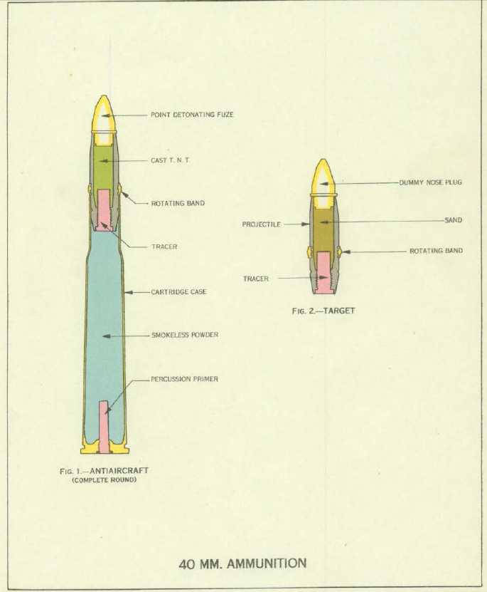
- ^The many Mods of USN ammunition were primarily bookkeeping designations used to indicate the manufacturer. USN AP had a windscreen. USN HE ammunition was issued in HE-T/SD, HE/SD, HE-I-T/SD and HE-I/SD forms. Plugged forms for training purposes were also manufactured. There was also a Mark 3 HE round that did not contain a tracer, but this was used only for a brief time during World War II and was replaced in 1945 by Dark (non-luminous tracer) and Dark Ignition (delayed ignition tracer) ammunition. Dark Tracer was issued only in HE/SD and HE-I-T/SD forms. Dark Ignition ammunition was issued only in HE-I-T-SD form.
- ^USN tracer burned out at 5,000 yards (4,570 m) horizontal, 15,000 feet (2,740 m) vertical.
- ^USN bourrelet diameter was 1.570 inches (39.88 mm).
- ^Bofors introduced their 40 mm PFHE proximity round during the 1980s. This was similar to those developed for their larger guns. Bofors claims a maximum effective bursting radius of 18 feet (5.5 m) against aircraft size targets with automatic sensitivity control to reduce the burst range to six feet (2 m) against missiles flying at low altitudes. As of 2001, Bofors was producing HE-T, AP-T and APHC-T (armor piercing high capacity - tracer) rounds for these weapons. The APHC-T round is unusual in that it carries an armor-piercing slug within an aluminum body. Bofors claims that this round penetrates some 30% deeper than the earlier AP-T round and that the aluminum body has an incendiary effect on the target.
- ^A Note on Sources: "The Bofors Gun" states that the "Weight of explosive filling" for the Bofors HE projectile was 285 to 300gms (0.628 to 661 lbs.) but I believe that this is actually the propellant weight, not the burster weight and have adjusted the values in this table accordingly.
- ^When first introduced, Bofors set the new-gun muzzle velocity at 2,789 fps (850 mps). The USA and UK adopted roughly this MV for the initial production of their weapons. As the USA gained experience and confidence in this weapon, they increased the MV to 2,890 fps (881 mps). The British adopted this MV for their cartridges loaded with USA-supplied nitrocellulose (FNH/PO22). Nitrocellulose was liked as its cooler-burning nature "considerably enhanced barrel life." - Gander. Postwar, most manufacturers including Bofors adopted an intermediate MV of 2,822 fps (860 mps).
- ^In "US Naval Technical Mission to Japan report O-47(N)-2" it is stated that the muzzle velocity of the Japanese weapon was 2,822 fps (860 mps) before the barrel was lengthened and the propellant charge increased. However, I must question if the working pressure given in this document - 16.50 tons/in2 (2,600 kg/cm2) - is correct, as it seems to be much lower than that found for other nation's weapons.
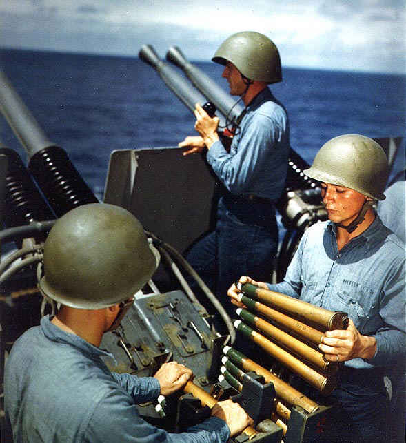
- Ammunition for most guns is held in four-round aluminum clips. The feed guides atop each gun can hold two clips at a time. Two loose rounds can be inserted between clips for a total of ten rounds in the autoloader. A four-round clip weighs about 19.0 lbs. (8.6 kg) to 20.0 lbs. (9.0 kg) depending upon type and propellant loading.
- As of 2001, ammunition for this weapon was still being produced by at least 10 countries including Bofors in Sweden.
| Type | Body Color | Band Color | Tip Color | Remarks |
|---|---|---|---|---|
| AP | Black | Black | Black | Plug in tracer |
| AP-T | Black | White | Black | None |
| HE-P | Green | Green | Green | Plug in base |
| HE-T/SD | Green | White | Green | None |
| HE/SD (DT) | Green | Black | Green | Dark Tracer |
| HE-I-T/SD | Green | White | Red | None |
| HE-I-P | Green | Red | Red | Plug in base |
| HE-I/SD (DT) | Green | Black | Red | Dark Tracer |
| HE-I-T | Green with Black Band | White | Red | No SD function |
| BL&T | Red | White | Red | Dummy Fuze |
| BL&P | Red | Red | Red | Dummy Fuze and Plug |
| HE-I-T-SD (DI) | Green | White | Red | Dark Ignition |
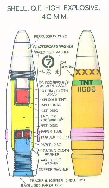
- The Mark and Mod, manufacturer's initials or symbol, and lot number are stamped around the body of the projectile.
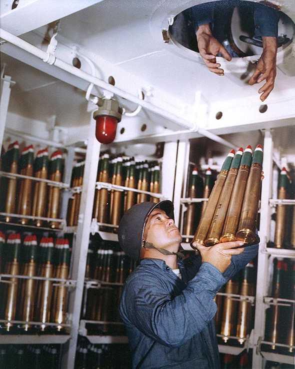
- Color photographs of some of these projectiles may be seen below.
| Elevation | Range | Angle of Fall | Time of Flight | Striking Velocity | Maximum Ordinate |
|---|---|---|---|---|---|
| 0.42 degrees | 1,000 yards (914 m) | 0.57 degrees | 1.23 seconds | 2,444 fps (745 mps) | 6 feet (2 m) |
| 0.70 degrees | 1,500 yards (1,372 m) | 0.98 degrees | 1.99 seconds | 2,116 fps (645 mps) | 16 feet (5 m) |
| 1.05 degrees | 2,000 yards (1,839 m) | 1.57 degrees | 2.88 seconds | 1,822 fps (555 mps) | 33 feet (10 m) |
| 3.53 degrees | 4,000 yards (3,658 m) | 7.13 degrees | 7.97 seconds | 1,050 fps (320 mps) | 269 feet (82 m) |
| 8.25 degrees | 6,000 yards (5,486 m) | 17.08 degrees | 15.00 seconds | 833 fps (254 mps) | 1,020 feet (311 m) |
| 15.43 degrees | 8,000 yards (7,315 m) | 30.40 degrees | 23.86 seconds | 740 fps (226 mps) | 2,595 feet (791 m) |
| 26.72 degrees | 10,000 yards (9,144 m) | 46.93 degrees | 36.04 seconds | 720 fps (219 mps) | 5,830 feet (1,777 m) |
| 42.00 degrees | 11,019 yards (10,076 m) | 61.95 degrees | 50.44 seconds | 778 fps (237 mps) | 11,000 feet (335 m) |
| 90.00 degrees | N/A | N/A | N/A | N/A | 22,800 feet (6,949 m) |
- ^Values for HE Shell from BuOrd OP 1188 page 2 and "Naval Weapons of World War Two" page 147. The muzzle velocity shown is the expected average MV over the life of the gun barrel.
- ^The maximum effective range with the Mark 51 control system was about 1,500 yards (1,370 m). With the post-war, radar equipped Mark 56 and Mark 63 systems the effective range was about 2,500 yards (2,290 m).
- AP projectiles had a blunter nose and as a result their maximum range was about 9,620 yards (8,800 m).
- USA produced HE-SD ammunition was set to self-detonate at 4,000 - 5,000 yards (3,700 - 4,570 m) so as to minimize problems due to "friendly fire." HE and AP rounds that did not self-destruct were also manufactured.
| Elevation | With HE Shell with no self-destruct |
|---|---|
| Range @ 45 degrees | 10,750 yards (9,830 m) |
| AA Ceiling | 23,500 feet (7,160 m) |
- ^Values for HE Shell from "Naval Weapons of World War Two" page 67.
- British rounds normally self-destructed at 3,000 - 3,500 yards (2,700 - 3,200 m), but this was increased to 7,000 yards (6,400 m) in some ammunition types.
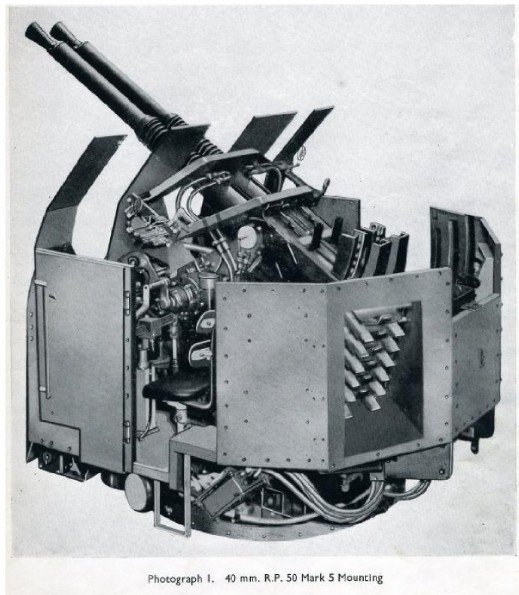
- The 1950 edition of B.R. 1919 "Handbook for 40 mm Bofors Twin R.P. 50 Mark 5 Mounting" states that the maximum effective range of this mounting was 2,500 yards (2,290 m) when used with the Close Range Blind Fire Director (CRBFD) and 1,200 yards (1,100 m) when used with the Simple Tachymetric Director (STD). The CRBFD was equipped with Type 262 radar while the STD was optronic. This document states that there was little difference in accuracy between the two director types and that "both show a considerable improvement on previous equipments." Please note, as this is a post-war document regarding directors placed in service after the war, these ranges may not reflect actual World War II performance.
| Elevation | With HE Shell |
|---|---|
| Range @ 45 degrees | about 12,250 yards (11,200 m) |
| Maximum AA Ceiling | 22,800 feet (6,950 m) |
| Effective AA Ceiling | 20,340 feet (6,200 m) |
- ^Values for HE Shell from "Kriegsmarine Prinz Eugen" page 73.
- German rounds self-destructed after 10.5 seconds.
| Elevation | With HE Shell |
|---|---|
| Range @ 50 degrees | 10,900 yards (10,000 m) |
| AA Ceiling @ 90 degrees | 26,250 feet (8,000 m) |
| Maximum effective range | 3,280 yards (3,000 m) |
- ^Values for HE Shell from US Naval Technical Mission to Japan report O-47(N)-2.
- The USN attributed this low effective range to "poor fuze design." It is unclear as to how the fuze design affected the effective range, but I would assume that this meant that the fuze was of poor aerodynamic shape. Self-destructing ammunition was not used.
| Range | Vertical Armor |
|---|---|
| 0 yards (0 m) | 2.70" (69 mm) |
| 2,000 yards (1,829 m) | 1.20" (30 mm) |
| 4,000 yards (3,658 m) | 0.60" (15 mm) |
| 6,000 yards (5,486 m) | 0.45" (11 mm) |
Note: This data is from "Battleships: United States Battleships 1935-1992" and is based upon the USN Empirical Armor Penetration formula. Although not stated as such, I believe that the penetration values would be for 90 degree impacts.
Prior to the start of World War II Bofors had produced 182 Land-Service guns for the Swedish Army and 295 for export. Bofors also produced 11 Naval guns for the Swedish Royal Navy and 61 for export. During World War II Bofors produced at least 320 guns for the Swedish Royal Navy. Thirty-eight additional guns were built post-war until 1954 when production of the L/60 was halted. Guns were of both air-cooled and water-cooled types and at least fifteen different single, twin and submarine mounting types were in Swedish service. Some of the twin water-cooled mounting types had integral 1.25 m or 2.0 m Hazemeyer rangefinders.
- Serious British interest in this weapon was first shown by the Army in 1933 and was followed by an order for 100 guns in 1937. Later, a manufacturing license was purchased from Bofors. The British version is officially listed as 56.3 calibers long. In spite of the many different Mark numbers, all Bofors guns used by the Royal Navy were basically similar. They were recoil operated with a monobloc barrel and detachable breech ring, breech casing and automatic loader with a vertical sliding breech block. The air-cooled Marks I, I* and III differed in details of the automatic loader and were primarily derivatives of Land Service (LS - Army) guns. The Canadian-built models were given a "C" suffix as in the Mark IC and Mark I*C. The Australian-built Mark I* was identical to the British-built gun of that designation. The water-cooled Marks IV, VIII, IX, X, XI and post-war NI and NI/I all had water jackets with circulating pumps and differed only in regards to the mounting they were to be used on. Single shots could be fired in all but the Mark VIII, IX, X and probably the NI and NI/I guns. Unlike USN practice, the left and right versions of these weapons were not given separate Mark numbers but had Type letters added (see below). This large number of variations of British Bofors guns compared to the three produced for the USN would seem to show once again the lack of interest by the Royal Navy in weapon standardization during the World War II period. The British considered the Bofors to be at least twice as effective as their own 2-pdr against torpedo bombers, but not much better than that weapon against kamikazes. This weapon was not used in large numbers on British ships with the largest totals being 14 on the escort carrier HMS Trouncer and 12 on the fleet carrier HMS Indomitable and the light fleet carrier HMS Ocean. Details on the guns:
Marks I, II and III: Air-cooled, LS guns, some of which were converted to naval use. See Note 3e below.
Mark IV and IV/I: Water-cooled. Designed for use on the twin-gun Mark IV Hazemeyer mountings. Produced in left and right versions, with Type D being the left gun and Type E the right gun. Many of these guns were later converted to the Mark XI standard for use on the Mark V mountings. A total of 484 guns were produced with 442 in service by 1945. See Note 4e below.
Mark V: Project abandoned
Mark VI: Army gun issued to Crusader AA tanks.
Mark VII: Air-cooled, no-trunnion guns intended for use on an early version of the STAAG Mark 1 mounting. 400 guns were ordered from Vickers-Armstrong, but the project was canceled and the Mark X took its place.
Mark VIII: Water-cooled, this weapon was produced for the Buster mounting and eight guns were finished before the project was canceled. Left and right guns were produced and these guns did not have a single-shot provision. See Note 12e below.
Mark IX: Air-cooled guns for the for the Mark VI six-gun mounting. Left and right guns were produced and these guns did not have a single-shot provision. See Note 6e below.
Mark X: Water-cooled guns for the STAAG Mark 2 mounting. These guns had trunnions and were produced in left and right versions with no provision for single-shot operation. See Note 11e below.
Mark XI: Water-cooled guns for the Mark V mounting. Many of these were converted from the Mark IV and Mark IV/I. Total of 342 in service by 1945.
- The USA provided 393 each of their Mark 1 (left-hand) and Mark 2 (right-hand) guns to the Royal Navy. These were used in British RP Mark I (Twin) and RP Mark II (Quad) mountings. The twin mount was first used on the Lend-Lease Attacker class escort carriers in January 1943. The quad mount was first installed on HMS Phoebe in June 1943. The USA also supplied air-cooled guns which were used mainly on LSTs.
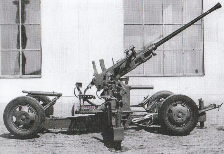
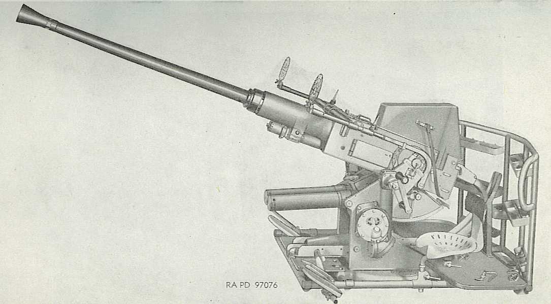
- The Mark III series of hand-operated single mountings were the Army design adapted for Naval use and were widely used, with some 500 in service by the end of World War II. Usually designated as LS Mark III (Land Service). The following mountings do not appear to have entered naval service, although they do appear on naval gun lists: Mark III* (hand operated with gyro sights for layer and trainer), RPLS Mark III (Remote Power Land Service) and Toadstool (joystick controlled power operation using Army components). Elevation limits for the Mark III were -5 to +90 degrees. As of June 1942, 314 Mark III mountings were in service, of which 301 were on DEMS. By May 1945, there were about 1,392 in service with 568 on DEMS. Those Army mountings modified at least somewhat for naval service were designated as Mark III CN and there were 500 of these in service at the end of the war, with 291 on DEMS. Mounting weight for the LS Mark III including the gun was 1.2 tons (1.22 mt).
- The Mark IV twin mounting was derived from the Hazemeyer triaxial mounting which had its origins in the 1940 arrival in Britain of the Dutch minelayer Willem van der Zaan. The Mark IV was a self-contained twin mounting that had its own rangefinder, radar and analog computer on the mount. This mounting used Mark IV water-cooled guns and utilized a track and pinion system for elevating and training which was powered via a Ward-Leonard system for automatic target tracking. The Mark IV was probably too advanced for its day and proved to be somewhat delicate for use on destroyers and sloops. The later STAAG and Buster designs were more robust, but very much heavier. According to service notes, the Mark IV was apparently used more often in manual mode than in power mode. Elevation was -10 to +90 degrees with cross-level of +/- 14 degrees with control cutting out at +/- 12 degrees. Maximum elevating speed was 25 degrees per second with the manually controlled joystick, but training and elevation via automatic control was limited to little more than 10 degrees per second. Weight was 7.05 tons (7.16 mt). The later Mark IV* mounting had a more robust radar attachment and differed in details of the controls and gyros. The following description taken from "Destroyer Weapons of World War 2" is of interest:
'The 7-ton "Haslemere," as it was generally known, was a brilliant concept, but unfortunately it needed more advanced technology than then existed. It cannot claim to have been the most popular of weapons but at least it provided a little light relief on occasions. When stationary in the "power-off" mode during maintenance, a combination of training, depression and cross-roll made it look for all the world as though it was about to fall off its gundeck. Observations like "I see the Haslemere is ill again" were common.'
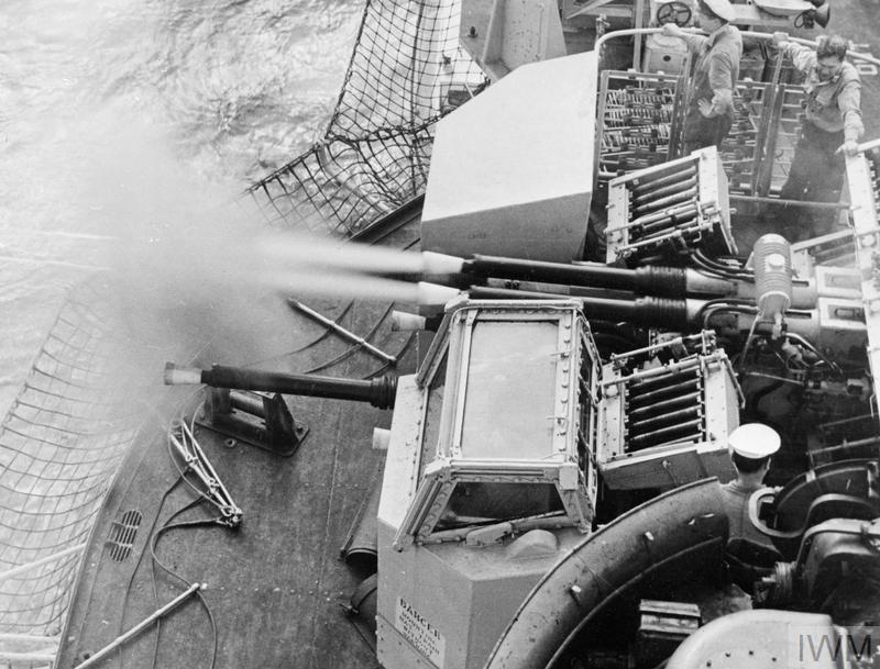
- The design of the Mark V twin was based upon the USN Mark 1 twin mounting adapted to use British components including some components of 2-pdr mountings and RPC gear from the 4.5" (11.4 cm) Mark V. Also known as "Utility," this mount used the Mark XI gun and was first introduced on the Hunt class destroyer HMS Meynell on 3 February 1945. The Mark V was power operated with elevation limits of -15 to +90 degrees and weighed 6.4 tons (6.5 mt) with 12 four-round clips carried on mount. Post-war, the minimum elevation was modified to -14 degrees. The Mark V proved quite popular in service and was retained in service long after the more sophisticated STAAG was retired. Its largest drawback was the lack of a blind fire capability. The RP50 Mark V had a maximum training speed of 35 degrees per second and elevating speed of 28 degrees per second. The RP50 Mark VC (Canadian) had a maximum elevation speed of 35 degrees per second.
- The Mark VI was a sextuple mount using the air-cooled Mark IX gun and used a 36-round ammunition tray for each gun rather than the usual four-round clips. Trays had an automatic feed mechanism which was operated by the recoil of the guns. Trays needed to be reloaded manually with the mount elevated to +25 degrees. Left and right versions of the guns were produced and the guns did not have a single-shot capability. Training and elevating speeds of the RP50 Mark VI mounting were both 30 degrees per second. This mount did not enter service until after the war. Weight was 21.24 tons (21.58 mt). This was a large weapons platform intended to be fitted primarily to battleships and fleet carriers with three hundred-twenty four being completed. The first battleship fitted was HMS Vanguard and she eventually carried a total of ten mountings although this number was rapidly reduced during her career. Aircraft carriers HMS Eagle and HMS Ark Royal carried eight. On some ships and some mountings, the lack of working space meant that the guns could only be reloaded at certain fixed bearings while on other ships the reloading could occur with the guns traversing at an automatically slowed rate.
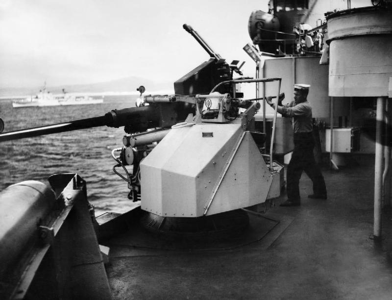
- The Mark VII was an adapted Army single mount with a weight of 1.40 tons (1.42 mt). Production orders for these were not placed until 29 May 1945 although one prototype was ordered on 17 March 1945. Similar in design to the "Boffin" mounting, described below, but able to elevate to +90 degrees and could train continuously as it used a slip ring for electrical power.
- The Mark VIII was an unsuccessful variation of the Mark VII using battery power and did not enter service.
- The Mark IX was an upgraded Mark VII mount with electric drive. The Mark IX mount used the Mark NI gun and had six ready-use clips on mount. Mark IX was used successfully during the Falklands War, with guns on HMS Fearless and HMS Intrepid shooting down an Argentine A-4B Skyhawk on 27 May 1982, probably the last aerial victory scored by a 40 mm/60. This success stimulated renewed interest in automatic weapons in the Royal Navy, eventually leading to the purchase of newer 20 mm and 30 mm weapons.
- The Boffin mounting was a twin 20 mm Oerlikon Mark V or Mark VC mounting modified to take a single Bofors 40 mm gun. Elevation was -10 to about +70 degrees. These used an oil hydraulic system and were fitted with a gyro gunsight. Elevation was restricted compared to other Bofors mountings as the position of the elevating trunnion axis was lower, due to the smaller nature of the Oerlikon guns. Some of these were still being used by the Canadian Navy in 1990 during the Persian Gulf war.
- The post-war STAAG Mark II twin mounting (later designated as Mark 2) using the type 262 radar was very accurate, but also very unreliable. Part of this unreliability appears to have been a result of the decision to mount the radar equipment directly to the gun mount, thus exposing it to a high level of vibration. At 17.5 tons (17.8 mt), it was also quite heavy for only a twin weapon. Used the Mark X gun. The hydraulically powered Mark II was called a "pseudo-triaxial" mounting and was unusual in that the third axis was a lateral deflection movement instead of being cross-roll. Training and elevating speeds were both 35 degrees per second. STAAG was found to be overly complicated and difficult to maintain and did not enjoy a long service life as a result. As noted, the type 262 radar was very accurate and there are stories of guns in action against towed targets where after shredding the sleeve the radar would track up the tow wire and the tow plane would escape only by cutting the wire. Nylon rope was eventually substituted for the wire as a remedy. The Mark I was the prototype single mounting. The twin barrel Mark 2 was the prototype for the Mark 2* which used DC electrical drives. The Mark 3 used AC drives. The Mark 2** had no radar in the mounting and was used for training.
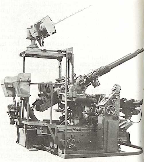
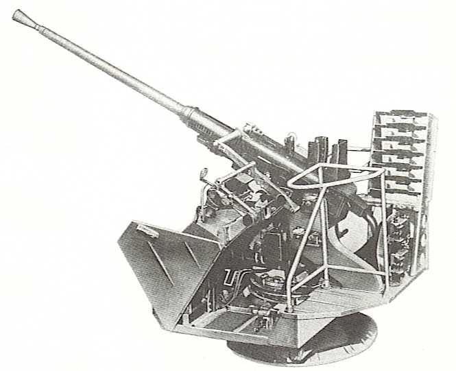
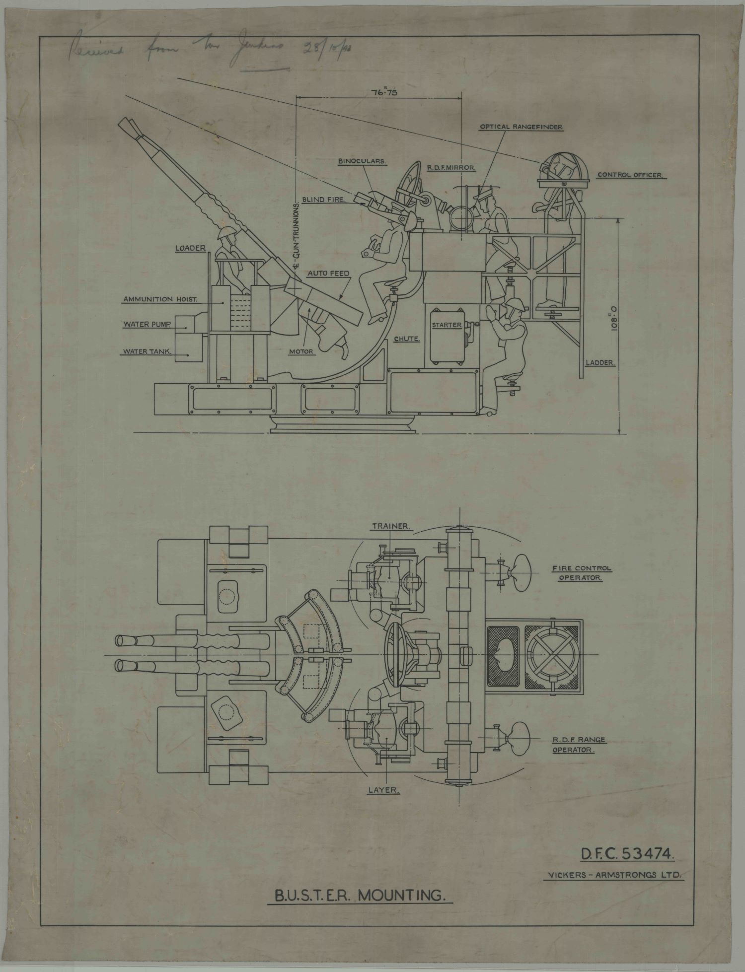
- The BUSTER (Bofors Universal Stabilized Tachymetric Electric Radar) twin was another World War II attempt at a self-contained mounting, but it was a very large platform and at approximately 20 tons (20.3 mt) this weighed far too much for only a twin arrangement and the project was canceled. Used the Mark VIII gun. See sketch below.
- Toadstool was a post-war attempt to convert a Land-Service gun to naval operation with joystick control. Extensively tested but did not enter service.
| Designation | Mark 1 Twin | Mark 2 Quad | Mark 3 Single | Mark 4 Quad |
|---|---|---|---|---|
| Weight
(no shield) |
9,800 - 13,000 lbs.
(4445 - 5897 kg) |
23,200 - 23,800 lbs.
(10,524 - 10,796 kg) |
2,440 - 4,200 lbs.
(1,107 - 1,905 kg) |
22,795 - 24,553 lbs.
(10,340 - 11,137 kg) |
| Elevation | -15 / +90 degrees | -15 / +90 degrees | -6 / +90 degrees | -15 / +90 degrees |
| Elevation Rate | 24 degrees / second | 24 degrees / second | See Note 1h | 55 degrees / second |
| Train | 360 degrees | 360 degrees | 360 degrees | 360 degrees |
| Train Rate | 26 degrees / second | 26 degrees / second | See Note 1h | 50 degrees / second |
| Recoil | Nominal: 7.9 in (20 cm) 2h | |||
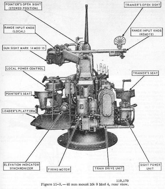
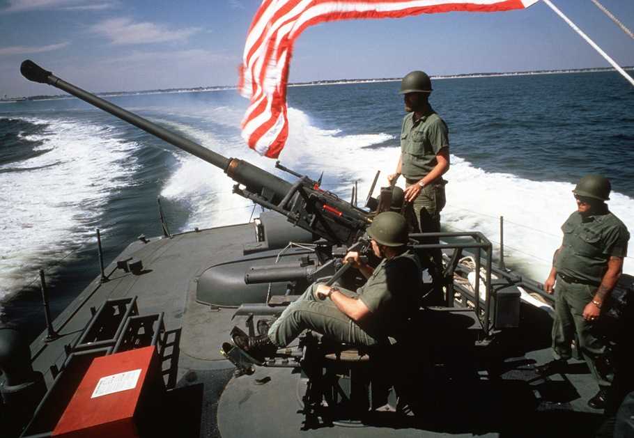
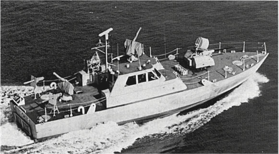
- ^1.11.2Mark 3 single mounts used air-cooled Navy M1 guns, which were modified versions of the US Army M1 Bofors gun. Three versions of the Mark 3 were used on surface ships, the Mod 0, Mod 4 and Mod 9, while submarines used the "wet mount" Mod 5 and Mod 6. Mod 0 was the basic Army mount and weighed 2,440 lbs. (1,107 kg) including gun and sighting mechanisms. The Mod 0 lacked power drives and so was manually trained and elevated. Crew for the Mod 0 was usually five to six men. Mod 4 added 1 hp power drives for training and elevation and had the same crew size as the Mod 0. These power drives differed from those made for the Army as the Naval mounts needed to be more powerful in order to compensate for the movements of the ship such as roll and pitch. Submarine Mods 5 and 6 were manually worked mountings. Most shipboard installations of manually worked single mounts had safety rails around them to keep the gun crews from accidentally firing into the ship. The Mark 3 Mod 9 was a much later design using rebuilt M1 guns. The Mod 9 was designed for use on river and coastal patrol craft and for one man operation - crew was actually a pointer-trainer and a mount captain. This mount used integral train and elevation power drives and was stabilized. Weight increased to 4,200 lbs. (1,905 kg). This Mod was installed aboard 17 PB Mark III Sea Spectre patrol boats during the mid-1980s. Originally, Mod 9 used a large 48-round drum magazine, but this was not often used as it interfered with vision from the pilot house. This ammunition drum looked something like the ones used on 20 mm Oerlikons guns but, of course, much larger. During the 1980s "Tanker War" in the Persian Gulf, it was reported that the drum did not feed reliably, so it was removed and the crews went back to manual loading.
- ^Recoil needed to be at least 7.2 inches (18.3 cm) to insure automatic operation of the weapon. Normal recoil varied from 7.7 to 7.9 inches (19.5 to 20 cm) with the maximum recoil being about 8.3 inches (21.1 cm).
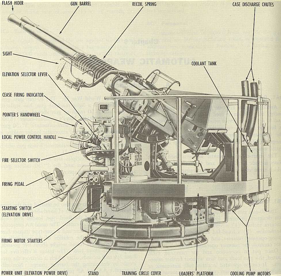
- All USN twin and quad mountings used water-cooled Mark 1 and Mark 2 Bofors guns. Any mod of the Mark 1 or Mark 2 Bofors guns could be used in any mod of USN twin or quad mountings; these USN guns were designed to be completely interchangeable in that regards. Twin mounts consisted of a left-hand gun (Mark 1) and a right-hand gun (Mark 2) joined together. The gun axes were 9.568 in (24.3 cm) apart. Elevation and training motors were 3 or 5 hp. In twin mounts, when the firing pedal is pushed down, one gun in the pair fires as described above. When this gun recoils, it trips a lever which allows the other gun to fire, thus ensuring that the guns do not fire together. For twin and quad mounts, the crew consisted of a Mount Captain, Pointer, Trainer, a 1st Loader for each gun and then however many ammunition passers it took to get back to the ammunition supply point. In addition to the guncrew, there was normally a Mark 51 (or later) Director crew consisting of a Pointer and a Range Setter.
- Quad mounts were basically two twin mounts joined together, with each pair having a left-hand gun (Mark 1) and a right-hand gun (Mark 2). The gun pairs axes were 60.0 in (1.524 m) apart. Elevation motors were 5 hp and training motors were 5 or 7.5 hp. Hydraulic drive gear was used on most twin mounts. Although both pairs of guns elevated together, in some Mods the pairs could be uncoupled in case of damage. As noted above, twin mounts fired one gun at a time. In quad mounts the same delay gear was used, which meant that one gun in each pair fired at the same time, thus preventing unbalanced forces and reducing dispersion.
- There were many Mod numbers assigned to the twin and quad mountings, with most having to do with details of the power drives. An asterisk (*) indicated that the mount included a radar antenna and was used with the Mark 63 director.
- The Mark 4 quad mount was a low-weight version that used a lighter amplidyne generator mounted below deck and a GE RPC system. This mounting had much faster training and elevation speeds than earlier mounts, but only 100 had been delivered by the end of the war.
- US ships carried large quantities of this weapon with USS Saratoga (CV-3) probably having the most with 23 quad mounts and two twin mounts for a total of 96 guns. Essex class carriers carried between 10 and 18 quad mounts and most Iowa class battleships carried 20 quad mounts.
- A Note on Sources: According to "U.S. Navy Bureau of Ordnance in World War II," the USN built more than 2,300 quad mounts, just under 10,000 twin mounts and more than 10,000 single mounts during the war. This mass production gradually reduced the cost, with quad mounts dropping from $86,000 down to $67,250 and twin mounts dropping from $62,300 down to $43,640. "The Bofors Gun" quotes different quantities for these mountings, but does not note the source for the numbers stated.
- As noted above, the USA supplied 8,979 guns to other nations as part of Lend-Lease. This is broken down as follows:
United Kingdom and Commonwealth: 2,834
China: 80
Free French Forces: 448
USSR: 5,511
American Republics: 4
Others: 2
As far as is known, only single mountings were ever used on warships and only HE and HE tracer was issued. The Kriegsmarine received a total of 578 guns for use on ships with an additional 247 guns delivered as coast-defense weapons. Naval Flak 28 mountings were set on a rotating ring attached to a round base plate that was fixed to the deck. Elevation was -6 / +90 degrees and training was 360 degrees.
The Type 5 (Model 1945) originated from the capture at Singapore in 1942 of 24 British Bofors single air-cooled guns in working condition and another 56 made serviceable after repairs. One of these was used to produce a Japanese copy and this underwent prototype firing trials in 1943 at the Torigasaki range of the Yokosuka Naval Arsenal. Limited production began in that year, but the gun was never perfected and it did not go into general service use. However, some 5 to 7 weapons a month were being produced in late 1944, apparently for service evaluation purposes. The main alteration from the British Bofors design was to increase the bore length to 94.49 in (2.400 m) - 60 calibers - and to add Rhienmetall-style flash suppressors, which proved unsatisfactory. Production was at the Yokosuka Naval Arsenal and at the Hitachi Manufacturing Company. Used only in manually-worked single mountings, which had an elevation range of -10 / +95 degrees and a weight of 1,870 lbs. (850 kg). Recoil was 8.5" (21.6 cm). Major problems found by the USN after the surrender were that poor manufacturing practices and lack of quality control caused improper seating of rounds and jamming of parts and that the star wheels and extractors were frequently mismated.
Nomenclature Note: Although the Japanese designation is normally described as the Type 5 (Model 1945), "US Naval Technical Mission to Japan report O-47(N)-2" at one point (page 16) describes the Mechanism designation as "Type 5 (1943)," which cannot be correct as the numbers do not match. This error may imply that the designation would actually be "Type 3" (Model 1943) which would seem to be more in keeping with the actual Japanese design date of 1943. However, it should be noted that the Japanese Model number system, normally based upon the year the breech design was started, became very chaotic towards the end of World War II, with new weapons having Type years that had no relationship to the actual year that the breech design was started. So, this weapon may indeed have been designated as Type 5.
Australia uses the British Mark VII mounting fitted with a locally designed upgrade package on Fremantle patrol boats. Elevation was -5 / +90 degrees and train was 360 degrees. Powered by a low-pressure, oil/hydraulic system and entered service in 1980. Training speed of 20 degrees per second and elevation speed of 40 degrees per second. Designated as 40/60 AN. A small number of these mountings were sold to Thailand.
The Republic of Korea has developed a modification kit for the USA Mark 1 twin mount which adds a stabilization system both to the gun mount and to the Mark 51 FCS. This kit improves their effectiveness against surface targets. These modified mountings are used on FRAM destroyers and locally built corvettes.
Hazemeyer was a Dutch subsidiary of Siemens Halske. Prior to World War II, this firm developed a very advanced triaxial mounting together with a tachymetric control system. As noted above, upon the Dutch defeat in 1940, this mounting was brought to Britain where it was immediately copied and introduced into production.






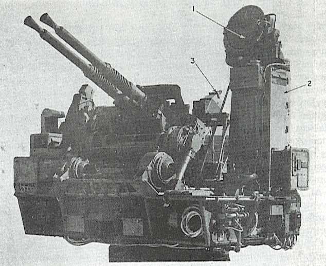
1. Type 262 Radar (3 cm)
2. Radar Operator's Panel
3. Control Officer's remote radar display
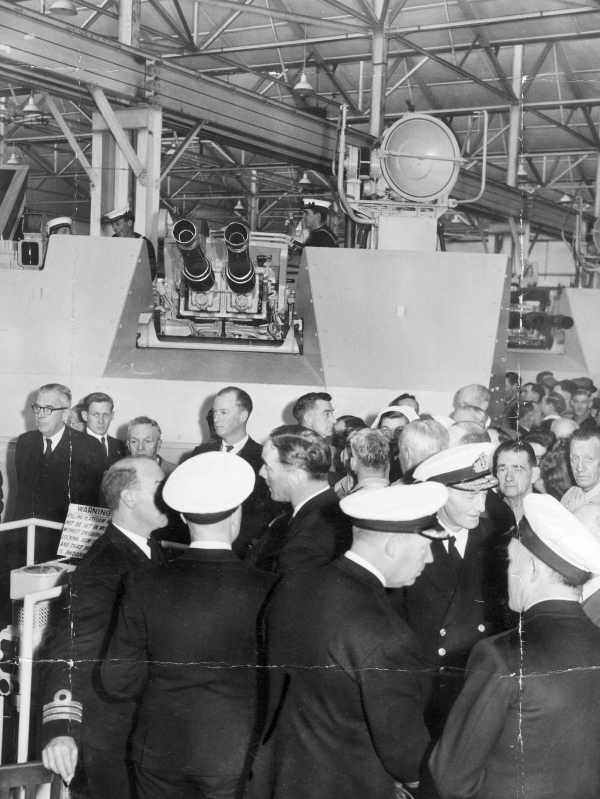
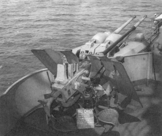


Images at The Vickers Photographic Archive
See Bofors
"The Design and Construction of British Warships 1939-1945: Volume I" edited by D.K. Brown
"Naval Weapons of World War Two" by John Campbell
"Joining the War at Sea" by Franklyn E. Dailey Jr., Capt. USNR (Ret.)
"The Illustrated Encyclopedia of 20th Century Weapons and Warfare" by Bernard Fitzsimmons
"US Battleships: An Illustrated Design History," "US Naval Weapons" and "The Naval Institute Guide to World
Naval Weapon Systems 1991/92" all by Norman Friedman
"German Warships 1815-1945 Volume I and Volume II" by Erich Gröner
"The Bofors Gun" and "Small Arms, Artillery & Special Weapons of the Third Reich" both by Terry J. Gander
"Jane's Ammunition Handbook: Ninth Edition 2000-2001" edited by Terry J. Gander and Charles Q. Cutshaw
"Destroyer Weapons of World War 2" by Peter Hodges and Norman Friedman
"Radar at Sea" by Derek Howse
"Weapon Direction in the Royal Navy" article by H.W. Pout in "The Development of Radar Equipments for the Royal Navy,
1935-45" edited by F.A. Kingsley
"U.S. Navy Bureau of Ordnance in World War II" by Lt. Cmdr. Buford Rowland, USNR, and Lt. William B. Boyd, USNR
"Champions of the Pacific" articles in "Warship Volume II" by Lawrence Sowinski
"Iowa Class Battleships" by Robert F. Sumrall
"German Naval Guns: 1939 - 1945" by Miroslaw Skwiot
"German Cruisers of World War Two" and "German Coastal Forces of World War Two" both by M.J. Whitley
"Kriegsmarine Prinz Eugen" by Steve Wiper
---
"Naval Ordnance and Gunnery - Navpers 16116-B - 1952" by Department of Ordnance and Gunnery, U.S. Naval Academy
"Ordnance Maintenance 40-MM Automatic Gun M1 TM 9-1252" by Department of the Army
"Ammunition: Instructions for the Naval Service: Ordnance Pamphlet 4 - May 1943" by Bureau of Ordnance (BuOrd), Department of the Navy
"40 MM Antiaircraft Gun - Ordnance Pamphlet No. 820 - October 1943" by Bureau of Ordnance (BuOrd), Department of the Navy
"Abridged Range Tables for U.S. Naval Guns: Ordnance Pamphlet No. 1188, 13 June 1944" by Bureau of Ordnance (BuOrd), Department of the Navy
"U.S. Explosive Ordnance - Ordnance Pamphlet No. 1664 - May 1947" by Bureau of Ordnance (BuOrd), Department of the Navy
US Naval Technical Mission to Japan report O-47(N)-2: Japanese Naval Guns and Mounts - Article 2, AA Machine Guns and Mounts
"Handbook for 40mm Bofors Twin R.P 50 Mark 5 Mounting - 1950: BR1919" by Naval Ordnance Department, Admiralty
---
"Ordnance Pamphlet No. 127: United States Naval Guns, Their Marks and Modifications - August 1956" at
Gene Slover's US Navy Pages
Maritime Park Association copy of B.R. 1919
---
Special help from Mark Fitzpatrick, Robert Hurst, Cliff McMullen, Robert Stoner and Vladimir Yakubov
Special thanks to Maciej Tomaszewski of Army 1914-1945 who found
many documents and photographs of Bofors guns in Polish service
31 August 2008 - Benchmark
23 September 2009 - Corrected typographical error, added comment about front-line service life
11 June 2010 - Added cutaway photograph of complete M81A1 AP round
01 November 2010 - Corrected range table for USN M81A1
11 January 2011 - Added data reference
14 January 2011 - Added cutaway sketch
06 April 2011 - Added data reference and added photographs of British Mark V twin mounting
07 June 2011 - Additional information about usage by Kriegsmarine
14 July 2011 - Added crew information for USN Twin and Quad Mounts
28 January 2012 - Added photograph of Polish twin mounting
16 June 2012 - Added photograph of STAAG in Australia
28 December 2013 - Minor additions and added photograph of HMS Sheffield
15 July 2014 - Added photograph of Sea Spectre Patrol Boat
09 October 2015 - Added photograph of Mark VI Sextuple mounting
24 December 2015 - Changed Vickers Photographic Archive links to point at Wayback Archive
06 February 2016 - Additional details on how the gun fired, Lend-Lease distribution, added Bofors ammunition
details and gun production, added information on British ammunition, mountings and weapons
15 June 2016 - Converted to HTML 5 format
07 April 2018 - Reorganized notes, added photographs of HMNS Van Kingsbergen and HMS Albion, and added
information on Swedish (Bofors) and German guns
07 May 2018 - Minor changes
21 June 2018 - Added information on Polish manufactured guns and added 1940 photographs of ORP Blyskawica
and ORP Sep mounting.
11 July 2018 - Minor changes regarding guns built for the USN
08 August 2018 - Minor changes regarding guns sent to Poland, added photograph of Polish submarine Orzel
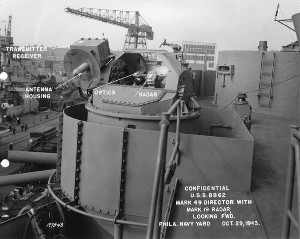
26 October 2019 - Added photograph of Mark 49 director and quantities on British warships
18 June 2020 - Added to operation description and recoil length
20 December 2020 - Additional information on USA production
23 January 2021 - Reorganized photographs
27 June 2021 - Added photograph of gun barrels on USS Alabama
31 October 2022 - Added more MV information
25 February 2023 - Corrected typographical error
22 August 2023 - Revised range table, minor other changes
20 November 2023 - Added sketch of BUSTER twin mounting
25 March 2024 - Corrected formatting problem
02 March 2025 - Corrected typographical error
