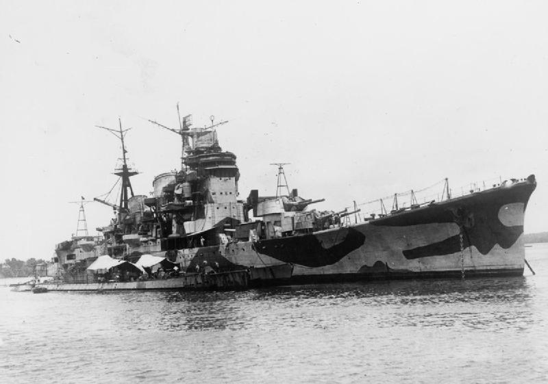
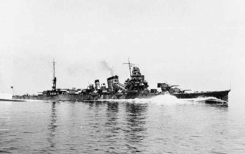
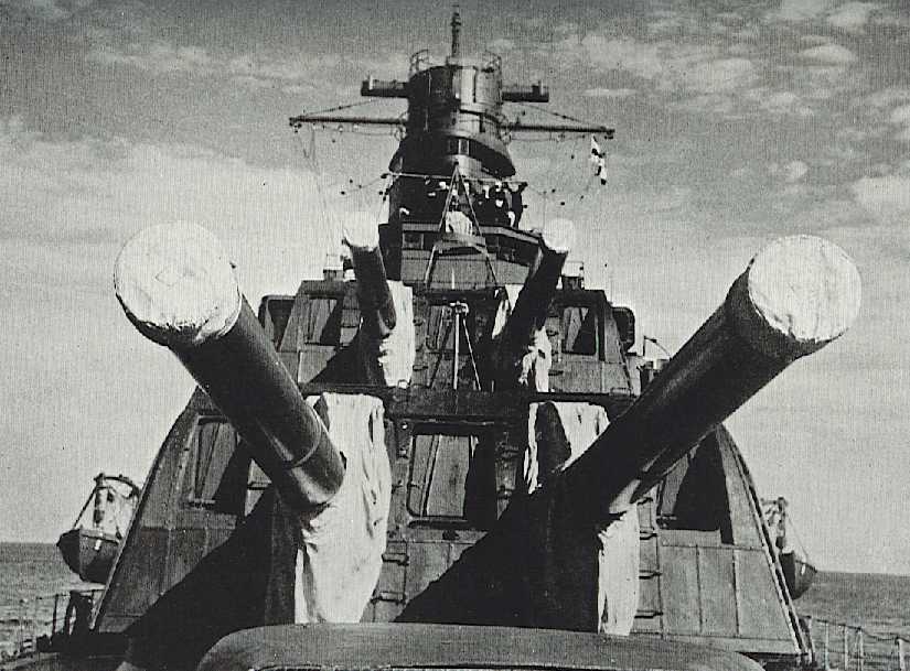
These guns were developed in 1930-1931 in order to achieve the maximum caliber allowed for cruisers under the Naval Limitation Treaties of the time. All heavy cruisers built after 1932 were armed with these weapons while older cruisers that had been originally armed with the 20 cm (7.9") 3rd Year Type No. 1 guns had them replaced with these more powerful weapons. In addition, the Mogami class cruisers had their 15.5 cm (6.1") triple mounts replaced by the 20 cm (8") No. 2 gun in twin mounts while the design of the Tone class was altered during construction to use these guns. By the start of the Pacific War, the changeover was complete and all Japanese heavy cruisers were armed with these weapons.
Some mountings were given high elevation capability with the idea that they could be used against aircraft, but the guns had a low rate of fire and the mountings could not train or elevate quickly enough to be effective in the AA role. As the surface fire control system was separated from the AA fire control system, switching from one to the other was a complicated process, resulting in a slow transition.
Large dispersion patterns were a problem with these ships during their early service life, with Takao in 1933 reporting patterns of 483 meters (530 yards) at a mean firing range of 19,300 meters (21,100 yards). In a target shoot against the old minelayer Aso (ex-Russian Armored Cruiser Bayan) in 1932, the cruisers Nachi and Myôkô repeatedly straddled at ranges between 15,800 and 22,300 meters (14,450 and 20,390 yards) yet failed to score a single hit because of dispersion patterns of about 350 meters (380 yards).
Much effort was put into reducing dispersion by stiffening the hull structure, following which the Myôkô class in 1936 achieved patterns of 280 to 330 meters (306 to 360 yards) at ranges of 20,000 to 22,000 meters (21,870 to 24,060 yards). The Japanese also introduced electro-mechanical aids, such as the Type 98 (Model 1938) Gunfiring Delay Installation which consisted of a "trigger time limiting device" which reduced the time of firing to less than 0.2 seconds after the circuit was made and a "firing time separator" which produced a lag of 0.03 seconds between the firing of each gun in a turret. This latter device was to make the shells leave each gun barrel at slightly different times, thus reducing their mutual interference in flight. These devices reduced dispersion by about 10-15%. Patterns for the 10-gun cruisers were reported by the USN as being very small at the Battle of Samar in 1944.
Nomenclature note: Even though these guns were developed in 1930 to 1931, they were still designated as 3rd Year Type (Model 1914). The No. 2 (2 GÔ) designation was used to distinguish these guns from the older 20 cm (7.9") 3rd Year Type No. 1 (1 GÔ) guns.
Actual bore diameter was 20.32 cm (8.0"). Constructed of A tube, full-length jacket, breech ring, breech bush and used a Welin screw block with a three-motion breech mechanism operated by hydraulic power or by hand.
| Designation | 20 cm/50 (8") 3rd Year Type (Model 1914) No. 2
Official Designation: 50 caliber 3rd Year Type No. 2 20 cm Gun |
|---|---|
| Ship Class Used On 1 2 | As Completed
Takao and Tone classes As Rearmed
As Planned
|
| Date Of Design | 1930 (actual design date) |
| Date In Service | 1932 |
| Gun Weight | 18.7 tons (19 mt) |
| Gun Length oa | 405.9 in (10.310 m) |
| Bore Length | 393.70 in (10.000 m) |
| Rifling Length | 333.9 in (10.310 m) |
| Grooves | (48) 0.090 in deep x 0.327 in (2.28 mm x 8.299 mm) |
| Lands | 0.197 in (5.00 mm) |
| Twist | Uniform RH 1 in 27.56 |
| Chamber Volume | 4,150 in3 (68.0 dm3) |
| Rate Of Fire | 3 to 4 rounds per minute 3 |
- ^All older heavy cruisers were rearmed with these guns by 1940.
- ^When it came time for Furutaka and Kako to be rearmed in the 1930s, production difficulties held up deliveries of the 20 cm (8") No. 2 guns intended for these ships. Rather than wait for these guns to be completed, the Japanese instead took 20 cm (7.9") No. 1 guns removed from Haguro and Ashigara, rebored and relined them to 20.32 cm (8"), and then installed them onto Furutaka and Kako. I would assume that any regunning during the war would have replaced these with the standard 20 cm (8") No. 2 guns.
- ^The ammunition supply system for the Aoba and Furutaka classes could provide three complete rounds per gun per minute while that for the later classes could provide a maximum of four complete rounds per gun per minute. As loading was at a fixed angle of +5 degrees and the gun elevation speeds were relatively slow, the rate of fire for these later classes was reduced at higher elevations to 2-3 rounds per minute at +55 degrees and a maximum of 2 rounds per minute at +70 degrees.
| Type | Bag |
|---|---|
| Projectile Types and Weights 1a | AP Type 91 2a: 277.4 lbs. (125.85 kg)
Common Type 91 HE 3a: 277.4 lbs. (125.85 kg) Common Type 0 HE 4a: 277.4 lbs. (125.85 kg) Common Type 3 IS 5a: 277.4 lbs. (125.85 kg) Illum Shell B 6a: 277.4 lbs. (125.85 kg) |
| Bursting Charge | AP Type 91: 6.9 lbs. (3.11 kg)
Common Type 91 HE: 18.0 lbs. (8.2 kg) Common Type 0 HE: 18.0 lbs. (8.2 kg) |
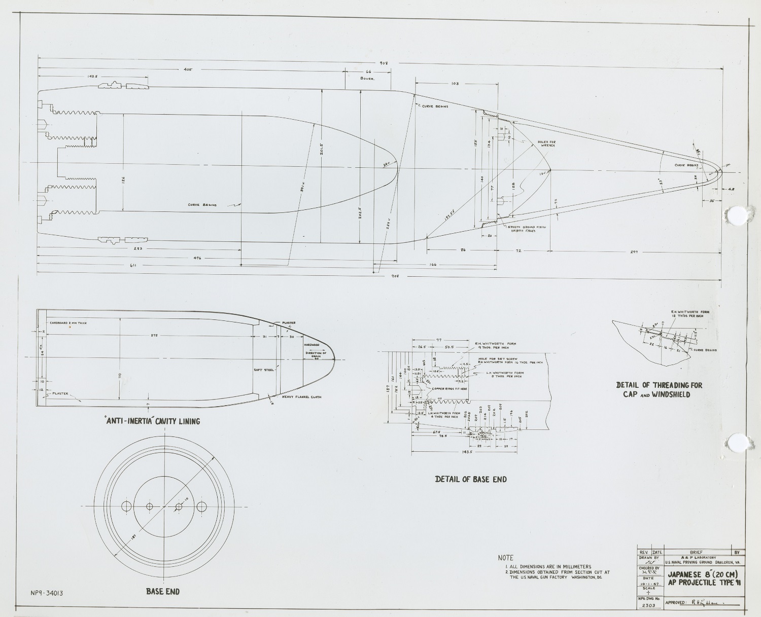
| Projectile Length | AP Type 91: 35.68 in (90.62 cm)
Common Type 91 HE: 35.83 in (91.0 cm) Common Type 0 HE: 34.65 in (88.0 cm) Common Type 3 IS: 34.07 in (86.55 cm) |
| Propellant Charge 7a | 74.5 lbs. (33.80 kg) 53 DC |
| Muzzle Velocity | All except Illum: 2,756 fps (840 mps)
Illum: 2,330 fps (710 mps) |
| Working Pressure | 19.9 tons/in2 (3,130 kg/cm2) |
| Approximate Barrel Life | 320 - 400 rounds |
| Ammunition stowage per gun | 120 - 126 rounds |
- ^In addition to the projectiles listed here, there were also Type 91 Exercise and Type 91 Timed Exercise shells.
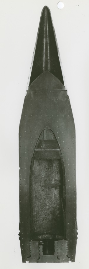
- ^Type 91 shells were all 6/∞ crh with boat tail and two copper driving bands. The diameter of the bourrelet was 7.960 in (20.218 cm). These 20 cm (8") Type 91 shells were not true "APC" projectiles as they lacked a cap, having only a cap head and windshield. Cap head and windshield together weighed 17 lbs. (7.7 kg). There were true APC projectiles, designated as Type 91 Mod 1, but these were used only for armor penetration experiments and were not in service use.
- ^Common Type 91 HE was issued starting in 1940
- ^Common Type 0 HE was supplied with time fuzes for AA defense. US Naval Technical Mission to Japan report O-19 says that this round had an effective radius of 32.05 yards (29 m) but this seems to be optimistic.
- ^IS is my abbreviation for the incendiary shrapnel round (sankaidan) intended for AA use. This was officially listed as a Common shell, but was actually an incendiary fragmentation round.
- ^The Shômeidan B Illumination round had an effective range of 17,500 yards (16,000 m) and an illuminating power of 1.6 million candelas. The maximum ballistic range was 24,900 yards (22,770 m).
- ^The propellant charge was in two bags which were rammed one at a time.
| Elevation | Distance | Striking Velocity | Angle of Fall |
|---|---|---|---|
| 2.4 degrees | 5,470 yards (5,000 m) | 2,133 fps (650 mps) | 3.0 |
| 5.3 degrees | 10,940 yards (10,000 m) | 1,634 fps (498 mps) | 7.5 |
| 10.5 degrees | 16,400 yards (15,000 m) | 1,299 fps (396 mps) | 15.8 |
| 18.0 degrees | 21,870 yards (20,000 m) | 1,194 fps (364 mps) | 29.0 |
| 30.0 degrees | 27,340 yards (25,000 m) | 1,247 fps (380 mps) | 47.0 |
| 40.0 degrees | 31,600 yards (28,900 m) | --- | --- |
| 45.0 degrees | 32,150 yards (29,400 m) | --- | --- |
According to "Japanese Cruisers of the Pacific War," the average maximum range for the 10-gun cruisers for daylight actions increased from about 16,840 yards (15,400 m) in 1924 to greater than 21,870 yards (20,000 m) by 1937 and the estimated hit projection increased from 3.0% at 21,870 yards (20,000 m) in 1930-34 to 6.0% in 1935-1940. The actual percentage of hits achieved during the war was much lower than these figures, a not unusual experience.
| Range | Side Armor | Deck Armor |
|---|---|---|
| 10,940 yards (10,000 m) | 7.5" (190 mm) | --- |
| 19,690 yards (18,000 m) | 4.7" (120 mm) | --- |
| 32,150 yards (29,400 m) | 2.9" (74 mm) | --- |
This data is from "Anatomy of the Ship: The Heavy Cruiser Takao" and refers to NVNC armor.
| Designation | Two-gun Mountings 1b Aoba (3): Modified Model C 2b |
|---|---|
| Weight | 163 - 172 tons (166 - 175 mt) |
| Elevation | Models C and D: -5 / +40 degrees 8b Model E: -5 / +70 degrees 9b Model E1, E2, Modified E2 and E3: -5 / +55 degrees |
| Elevation Rate | Models C, D: 6 degrees per second
Models E and E1: 12 degrees per second 9b E2, Modified E2 and E3: 6 degrees per second |
| Train | About +120 / -120 degrees |
| Train Rate | 4 degrees per second |
| Gun recoil | N/A |
| Loading Angle | +5 degrees 10b |
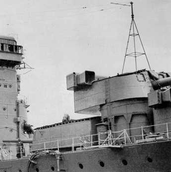
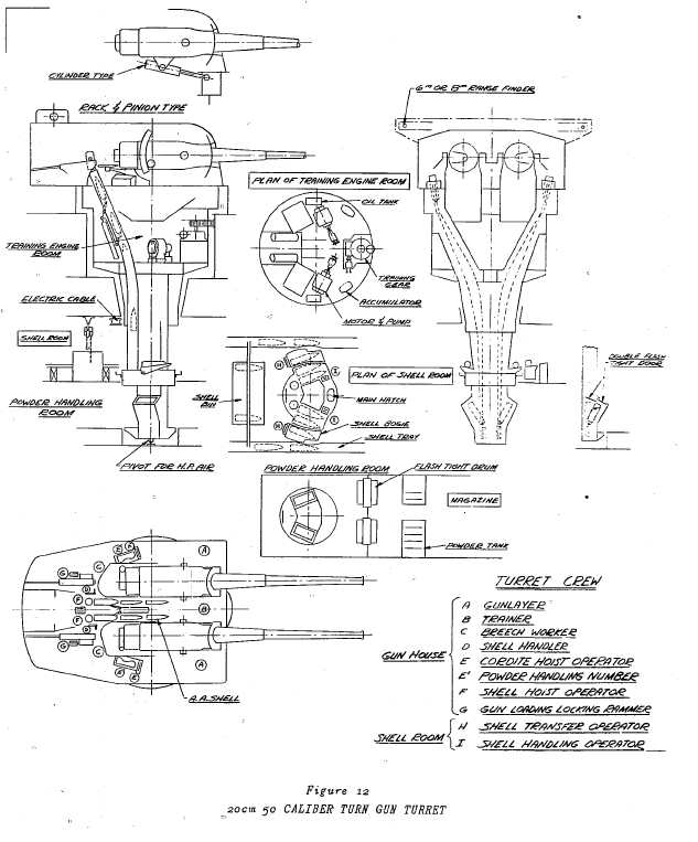
- ^These mountings varied in detail from class to class and even within a class but many features were the same. They were all operated with very noisy electric motor driven oil hydraulic pumps located in the revolving structure. Damage to rubber covered wiring by oil leaks was a common complaint. Run out was by compressed air. Elevation was by rack and pinion on the Model C, D and E1 mountings and by hydraulic actuators on the other Model E mountings. The Modified E2 and the Model E3 mountings had 315 inch (8 m) rangefinders, the other Models had 236 inch (6 m) rangefinders.
- ^2.12.2As originally completed in the 1920s, the Model C and Model D mountings used pusher hoists for the powder charges that effectively created a continuous powder train between the gun breeches and the magazines. These powder hoists were replaced by bucket hoists in 1930s which gave improved protection from flash. Shell hoists remained pusher types. Flashtight doors were fitted to all shell and powder hoists at both the lower and upper ends. Revolving flash tight scuttles were fitted between the magazines and powder handling rooms. These changes did slow down the supply rate of ammunition to four charges per minute. However, the new arrangements proved their worth in the summer of 1935 when a flareback wrecked Turret No. 2 on Ashigara. Although 41 men were killed or injured, the flash did not penetrate down into the magazines and the ship was saved.
- ^Model E and Model E1 mountings had two shell hoists per gun, while all other Models had one. The second hoist was intended to support anti-aircraft firing by making it easier to change ammunition types, but they resulted in a larger turret trunk, a larger lower chamber, increased turret weight and added crewmen. As loading was performed at +5 degrees and the training and elevation speeds were relatively slow, the reality was that these mounts were of little use for anti-aircraft defense. All Model E mountings incorporated the improved flashtightness introduced on the Modified Model C and D mountings including using bucket hoists for ammunition supply. The gunhouses for all Model E types were 15 cm (5.9") taller than the Model D gunhouse in order to better accommodate the larger guns.
- ^Model E mountings (and the Model B mountings used on Akagi and Kaga) differed from earlier mountings in having flat instead of sloped roofs and in that the rangefinders were partially within the mounting instead of being superimposed. The entry doors on the rear of these Model B and Model E mountings had a curved top while the doors on the earlier Models were rectangular.
- ^During modernization and replacement of the 20 cm (7.9") No. 1 guns with the 20 cm (8") No. 2 guns, the Furutaka class was converted from six Model A single mounts to three Model E2 twin mounts. Although externally these looked like the Model E mounts, internally the gunhouses and ammunition supply arrangements including hoists resembled the Model C mountings used on the Aoba class.
- ^The original Naval General Staff requirements for the Mogami class as issued in 1930 called for the design to mount 15.5 cm guns in triple turrets but be able to have these replaced by 20 cm guns in twin turrets should the treaty be revoked or in case of emergency. However, the design of the triple 15.5 cm turret needed a larger roller race than the twin 20 cm mounting. As a result, when the Mogami cruisers were regunned in 1939/1940, their Modified E2 turrets needed a larger diameter roller path than the other E Models in order to fit the larger diameter roller path used for the 15.5 cm turrets. These turrets were also somewhat longer than the other Model E gunhouses in order to accommodate the larger roller path. As the 20 cm guns were longer than the 15.5 cm guns they replaced, the guns of No. 2 turret could not depress below +12 degrees when trained on the centerline as otherwise they would have struck No. 1 turret. These problems seem to indicate that little effort was expended during the initial design phase to meet the regunning requirement or that the designers were unable to come up with a solution that still met the very tight tonnage limits on this class.
- ^The hull and barbettes of the Tone class had already been completed up above the armored deck when the main armament was changed from triple 15.5 cm turrets to twin 20 cm turrets. As described above for the Mogami class mountings, as the twin 20 cm turret needed a smaller diameter roller path than the triple 15.5 cm turret, this meant that the diameter of the completed portion of the barbettes was now too large to fit the standard turret races used for twin 20 cm turrets. To compensate, the design for the top of the barbettes was altered to a conical shape with a diameter of 18.7 feet (5.70 m) at the lower level and 16.4 feet (5.00 m) at the upper level. The follow-on Ibuki class were to use the same E3 turrets as the Tone class, but these later ships were designed from the start with 16.4 foot (5.00 m) diameter barbettes. However, the distance between the centerlines of No. 1 and No. 2 barbette on the Ibuki class was the same as for the Mogami class, which meant that the guns in No. 2 turret would have still have needed to be raised in order to clear No. 1 turret, similar to the problem with the Mogami class.
- ^When converted to the No. 2 guns, the Model C and Model D mountings were modified to handle the larger guns and maintain their maximum elevation of +40 degrees. Some accounts infer that Aoba was later modified to increase maximum elevation to +50 degrees, but this is not supported by "Japanese Cruisers of the Pacific War."
- ^9.19.2The maximum elevation of the Model E was +70 degrees and elevation speed increased to 12 degrees per second, but the elevating and recoil mechanisms proved to be fragile and it was found that +55 degrees was the maximum practical elevation. As a result, the other Model E mountings were designed for a maximum elevation of +55 degrees and had their elevation speed reduced to 6 degrees per second.
- ^Note that as Turret 2 on the Mogami class could not depress below +12 degrees when trained on the centerline and that the loading angle was +5 degrees, this meant that the guns in this turret could not be loaded until they were trained outwards enough to clear Turret 1.
- The gun axes were 74.8 in (190 cm) apart for all Models.
- Model C, Model D and those Model E mountings with one shell hoist per gun had a crew of 19 in the gunhouse, nine in the shell room and ten more in the powder magazine. Those Model E mountings with two shell hoists per gun had a crew of 23 in the gunhouse, nine in the shell room and ten more in the powder magazine.
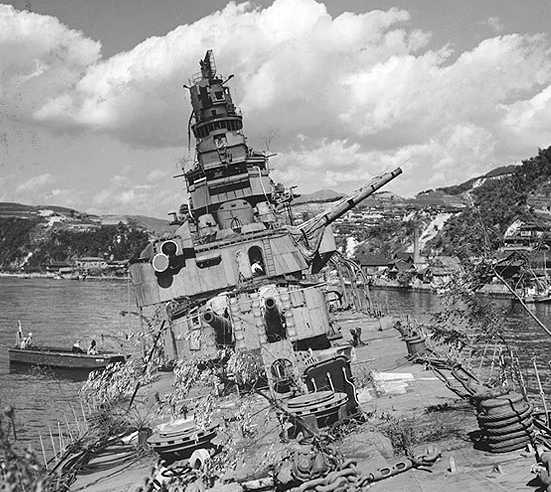
- Maya was badly damaged at Rabul on 5 November 1943 by aircraft from USS Saratoga (CV-3). She was sent back to Japan for repairs and then converted into an AA cruiser. Her number 3 turret and all 12 cm (4.7") AA guns were removed and she was then modified such that she now carried eight 20 cm (8.0") No. 2 guns and twelve 12.7 cm/40 (5.0") AA guns along with thirty-five 25 mm and thirty-six 13 mm MGs. It had been planned to similarly convert sister-ship Chokai, but this was not carried out.
- Mogami was badly damaged by bombing and by collision with sister-ship Mikuma during the Midway battle in June 1942. During repairs, it was decided to convert her to a seaplane carrier. This conversion saw the removal of number 4 and number 5 turrets which were replaced by a flight deck and hanger facilities for carrying eleven E16A1 "Paul" reconnaissance floatplanes. As these planes were not available at the time of her conversion, she was instead given seven older floatplanes. Mogami exited the shipyard now armed with six 20 cm (8.0") No. 2 guns, eight 12.7 cm/40 (5.0") AA guns and thirty 25 mm guns in ten triple mounts.

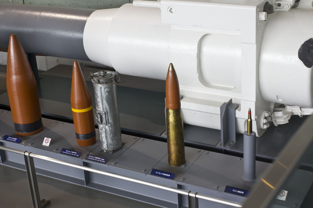
30 cm main gun shell
20.32 cm Common shell
20.32 cm powder canister
12.7 cm high angle gun shell
25 mm machine gun shell
"Naval Weapons of World War Two" by John Campbell
"The Japanese Warships of the Pacific War" by The Koku-Fan
"Japanese Cruisers of the Pacific War" by Eric Lacroix and Linton Wells II
"The Japanese Super Battleship Strategy" article by Hans Lengerer in "Warship Volume VII"
"Anatomy of the Ship: The Heavy Cruiser Takao" by Janusz Skulski
"Cruisers of World War Two" by M.J. Whitley
---
US Naval Technical Mission to Japan report O-19: Japanese Projectiles General Types
US Naval Technical Mission to Japan report O-47(N)-1: Japanese Naval Guns and Mounts-Article 1, Mounts Under 18"
NPG Report No. 269: Ballistic Test and Metallurgical Examination of Japanese 8", 14", 16" and 18" Armor Piercing Projectiles
---
Special help from Kosaku Ariga (Jarek) and James Poynor
31 December 2007 - Benchmark
27 May 2012 - Updated to latest template
07 August 2012 - Added information on the Tone and Ibuki class mountings
11 September 2012 - Added mounting information
16 December 2013 - Updated photograph of Myôkô
20 June 2014 - Corrected note regarding regunning of the Mogami class
20 September 2014 - Added notes about Maya and Mogami conversions
11 April 2015 - Added mounting crew details
01 November 2015 - Added projectile photograph
20 December 2015 - Added photograph of Furutaka
14 May 2017 - Converted to HTML 5 format, added information on APC projectiles from NPG Report No. 269
14 November 2017 - Corrected typographical error
07 February 2018 - Reorganized notes
15 August 2018 - Minor changes
20 March 2019 - Added note regarding time fuzes on Common Type 0 HE
31 July 2019 - Added comments about modifications to C and D mountings and Mogami class loading problems
31 July 2021 - Minor changes for clarity
08 October 2022 - Corrected typographical error
