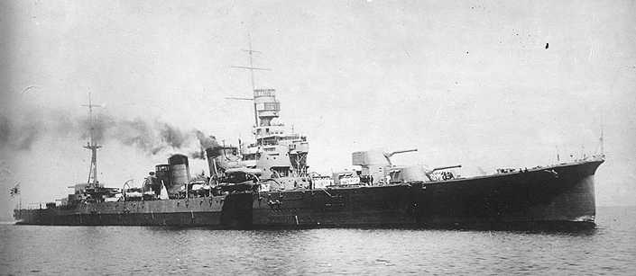
Designed for a new generation of scout cruisers shortly after World War I, this weapon was also used by the Myôkô class heavy cruisers and on the aircraft carriers Akagi and Kaga. As the cruisers were rebuilt in the 1930s, these guns were then replaced by the more powerful 20 cm/50 (8") 3rd Year Type No. 2 Gun.
The aircraft carriers Akagi and Kaga as completed had these guns in both twin turrets and in single casemate mountings. When modernized in the 1930s, the twin mountings were removed from both ships. By the start of the Pacific War, these two carriers were the only Japanese ships still armed with these weapons and they carried them until they were sunk at the Battle of Midway.
Many of these guns were later used in coastal batteries to defend the Japanese homeland islands.
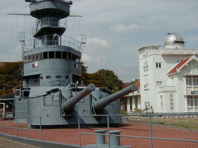
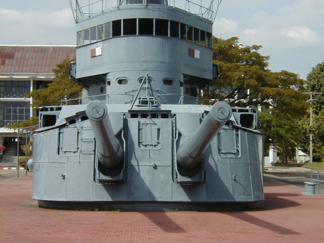
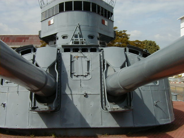
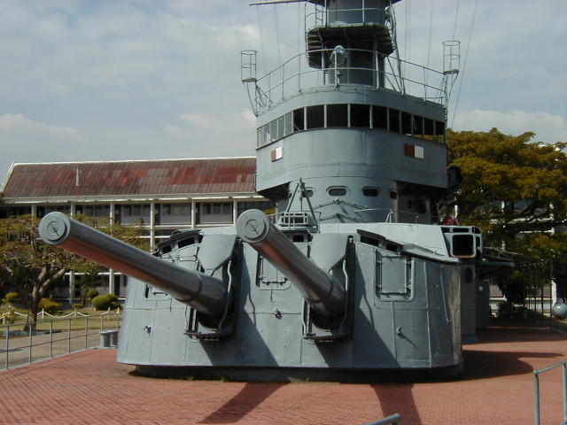
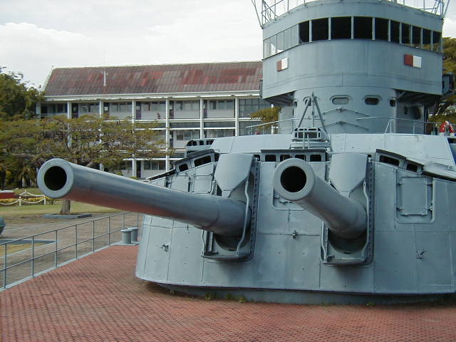
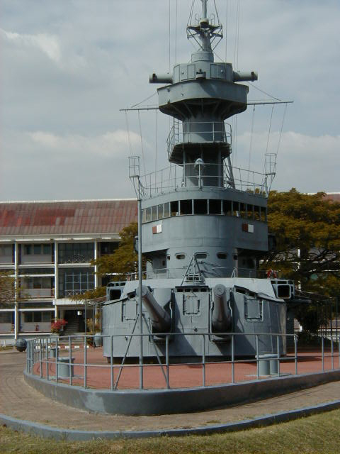
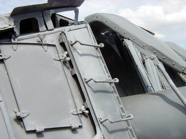
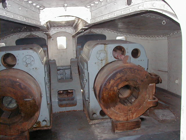
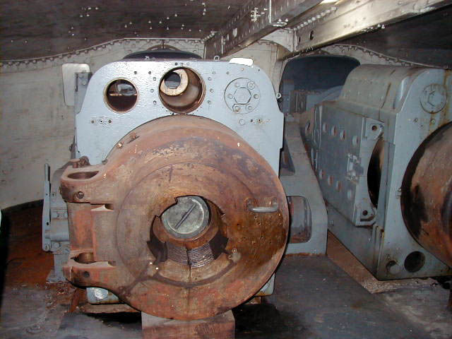
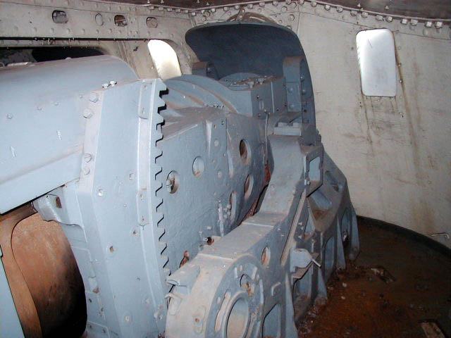
One of the twin mountings and its guns still survives as a memorial in Thailand. See the Thonburi Memorial section and Mount / Turret note below.
Nomenclature note: The No. 1 (1 GÔ) designation was added to these guns after the more powerful 20 cm/50 (8") 3rd Year Type No. 2 (2 GÔ) Gun was adopted on 6 April 1931.
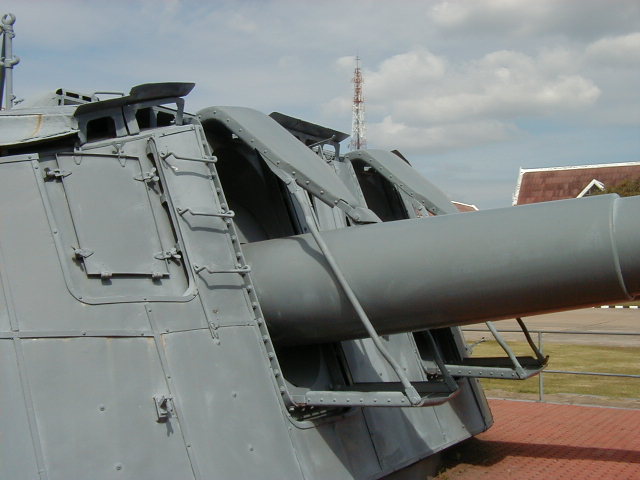
Actual bore diameter was 20.0 cm (7.87"). These guns were wire wound for part of their length and had Welin screw breech blocks with a three-motion breech mechanism. These weapons can be distinguished from the 20 cm/50 (8") No. 2 guns by the marked step in the chase diameter.
| Designation | Original Designation: 20 cm/50 (7.9") 3rd Year Type (Model 1914)
Redesignation April 1931: 20 cm/50 (7.9") 3rd Year Type (Model 1914) No. 1 Official Designation: 50 caliber 3rd Year Type No. 1 20 cm Gun |
|---|---|
| Ship Class Used On | Japan
Aircraft Carriers: Akagi and Kaga Heavy Cruisers: Furutaka 1, Aoba and Myôkô classes Thailand
|
| Date Of Design | 1920 2 |
| Date In Service | 1923 |
| Gun Weight | 17.6 tons (17.9 mt) |
| Gun Length oa | 393.7 in (10.000 m) |
| Bore Length | 381.5 in (9.144 m) |
| Rifling Length | N/A |
| Grooves | 48 |
| Lands | N/A |
| Twist | N/A |
| Chamber Volume | N/A |
| Rate Of Fire | Furutaka class 3: Less than 2 rounds per minute
Others: 3 to 5 rounds per minute |
- ^When it came time for Furutaka and Kako to be rearmed in the 1930s, production difficulties held up deliveries of the 20 cm (8") No. 2 guns intended for these ships. Rather than wait for these guns to be completed, the Japanese instead took 20 cm (7.9") No. 1 guns removed from Haguro and Ashigara, rebored and relined them to 20.32 cm (8"), and then installed them onto Furutaka and Kako. I would assume that any regunning during the war would have replaced these with the standard 20 cm (8") No. 2 guns.
- ^Design was started in 1916 at the Kure Navy Yard but not finalized until much later. The prototype gun was proved in 1921.
- ^The intended rate of fire for the Furutaka classes as designed was 3 to 5 rounds per minute. However, they had a very complex ammunition supply system which reduced the realistic ROF to the figure given above. In addition, moving the shells and charges required a good deal of manual labor, which meant that even this low rate could not be sustained for long periods.
| Type | Bag |
|---|---|
| Projectile Types and Weights 1a | APC Type 5 2a: 242.5 lbs. (110 kg)
APC No. 6 / Type 88 3a: 242.5 lbs. (110 kg) Common Type 4 HE 4a: 242.5 lbs. (110 kg) |
| Bursting Charge | APC Type 5: 6.4 lbs. (2.9 kg)
APC No. 6 / Type 88: 6.3 lbs. (2.84 kg) Common Type 4: 16.1 lbs. (7.3 kg) |
| Projectile Length | 30 in (76.2 cm) |
| Propellant Charge 5a | APC Projectiles
71.76 lbs (32.55 kg) 60 DC 71.76 lbs (32.55 kg) 70 C2 71.76 lbs (32.55 kg) 80 C2 71.76 lbs. (32.55 kg) 53 DC Common Projectiles
|
| Muzzle Velocity | 2,854 fps (870 mps) |
| Working Pressure | 19 tons/in2 (3,000 kg/cm2) |
| Approximate Barrel Life | 300 rounds |
| Ammunition stowage per gun | 120 rounds |
- ^Surface and AA exercise shells were also provided for these guns.
- ^APC Type 5 was adopted on 15 June 1925. APC Type 5 was superseded by the APC No. 6 which was adopted on 17 November 1928.
- ^APC No. 6 was essentially similar to the Type 5 in terms of armor penetration but was better protected from premature detonation and had enhanced underwater performance. APC No. 6 was redesignated as the Type 88 on 6 April 1931. It appears that no APC Type 91 was ever created for these guns.
- ^Common Type 4 HE was redesignated as simply "Common" on 6 July 1932.
- ^The propellant charge was in two bags.
| Elevation | Distance |
|---|---|
| 25 degrees | 26,250 yards (24,000 m) |
| 40 degrees | 29,200 yards (26,700 m) |
| 45 degrees | 30,620 yards (28,000 m) |
These figures are from "Japanese Cruisers of the Pacific War" but "Naval Weapons of World War Two" says that the range @ 25 degrees was 24,700 yards (22,600 m) during World War II. This may be the result of different propellants being used during World War II.
| Designation | Single Mounts
Furutaka (6) (as built - all were removed during 1930s modernizations): Model A 1b Akagi (6) and Kaga (6) (as built): Model A1 2b 3b Akagi (6) and Kaga (10) (after modernization during 1930s): Model A1 Two-gun Turrets 4b Thailand
|
|---|---|
| Weight | Model A Single Mount: 56.6 tons (57.5 mt)
Model B Twin Turret: N/A, but probably about 172 tons (175 mt), the same weight as the Model E with rangefinder Model C and Model D Twin Turrets: 154.5 tons (157 mt) |
| Elevation 10b | Model A and Model A1 Single Mounts: -5 / +25 degrees 11b Model B Twin Turrets: -5 / +70 degrees Model C and Model D Twin Turrets: -5 / +40 degrees |
| Elevation Rate | Model A Single Mounts: N/A
Model B Twin Turrets: N/A (probably the same 12 degrees per second achieved by the Model E) Model C and Model D Twin Turrets: 6 degrees per second |
| Train | Cruiser Single Mounts
All except Mounts III and IV: About +150 / -150 degrees Mounts III and IV: About +20 / +160 degrees to either side Cruiser Twin Mounts
Carrier Single and Twin Mounts: About +20 / +160 degrees |
| Train Rate | Model A Single Mounts: N/A
Model B Twin Turrets: N/A (probably the same 4 degrees per second achieved by the Model E) Model C and Model D Twin Turrets: 4 degrees per second |
| Gun recoil | N/A |
| Loading angle | Model A, Model A1 and Model C: +5 to +9 degrees
Model B and Model D: +5 degrees |
- ^The Model A mounting was a simple gunhouse with a one-deck deep semi-stalk going to a handling room directly below the mounting. Training was by a 14 hp electro-hydraulic motor while elevation was via an 8 hp electric motor. As noted above, ammunition supply was complex and required much manual labor for both shells and powder bags. Magazines and shell rooms were at the same level below the armored store deck. Shells and powder bags were moved by hand from their storage locations to lower hoists which raised them to the handling room at a rate of six complete rounds per minute. Shells and bags were then pushed manually through an opening of the ring support tube (barbette) where the shells were placed on an upper hoist that delivered them to the gunhouse. Both upper and lower shell hoists lifted the shells horizontally. Powder bags were passed by hand from the handling room to the gun house. Loading and ramming of both projectiles and powder bags was by hand. These single mountings were replaced by twin mountings during the 1930s rebuilds.
- ^The Model A1 single mounts used on the carriers were essentially the same as Model A single mounts but were installed in casemates rather than in gunhouses.
- ^The twin mountings varied in detail from class to class and even within a class but many features were the same. They were operated with very noisy electric motor driven oil hydraulic pumps located in the revolving structure. Damage to rubber insulated wiring by oil leaks was a common complaint. For all models, run out was by compressed air, the breech blocks were manually operated and time fuzes were set on the loading tray.
- ^The Model B mountings used on the carriers Akagi and Kaga were designed later than the Model C and D mountings. The design of the Model B was nearly the same as the Model E used on the Takao class heavy cruisers, the major difference being that the Model B used the 20 cm (7.9") 3rd Year Type No. 1 guns while the Model E used the 20 cm (8") 3rd Year Type No. 2 guns. Like the Model E mounts, Model B mounts had two shell hoists per gun, while the Model C and D mounts had one shell hoist per gun. The second hoist was intended to support higher angle (anti-aircraft) firing by making it easier to change ammunition types, but they resulted in a larger turret trunk, a larger lower chamber, increased turret weight and added crewmen. As loading was performed at +5 degrees and the training and elevation speeds were low, the reality was that these mounts were of little use for anti-aircraft defense. These twin mountings were removed from Akagi and Kaga during their reconstruction in the 1930s and after that time they carried only single 20 cm (7.9") guns in casemate mountings.
- ^Model C mounts for the Aoba class were designed later than the Model D mounts for the Myôkô class. The design of the Model C was basically that of the Model D with the stalk adapted to fit the magazine and shell room arrangements of the Aoba class. These were the same as the Furutaka class with the shell and magazine spaces on the same level. Initial firing trials on the Aoba class showed vibration problems, primarily as these twin mountings were really too large for the size of the hull. Accordingly, the hull and deck around No. 3 turret were strengthened.
- ^The Model D on the Myôkô class differed in having the shell rooms located under the magazines and the turret stalk was accordingly longer. Supply arrangements for Aoba and Myôkô had more mechanical assistance than those for the earlier Furutaka class, giving them a higher rate of fire. Shells were transported from storage via a tackle arrangement and then moved manually to handling room trays located around the barbette which passed them into the barbette. From the tray projectiles were loaded manually into the shell hoists via a shell dolly which followed the hoists as they rotated with the turret. For both Model C and Model D, each gun had its own shell and powder hoist which could supply five complete rounds per minute. Shell and powder bag hoists were of a "pusher" type and both projectiles and powder bags were delivered vertically to the gunhouse. The powder bag pusher hoists effectively created a continuous powder train between the gun breeches and the magazines. This design flaw was not corrected until the ships were rearmed during the 1930s rebuilds. Projectiles were loaded and rammed hydraulically, while powder bags were loaded by hand into the breech and then rammed hydraulically. Training for twin mounts was by a 50 hp electric motor which drove hydraulic gear. Elevation was by rack and pinion. A 75 hp motor drove two hydraulic pumps which provided power to a common ring. This ring supplied hydraulic actuators for elevating the guns, ramming and the ammunition hoists. Model D had 236 inch (6 m) rangefinders.
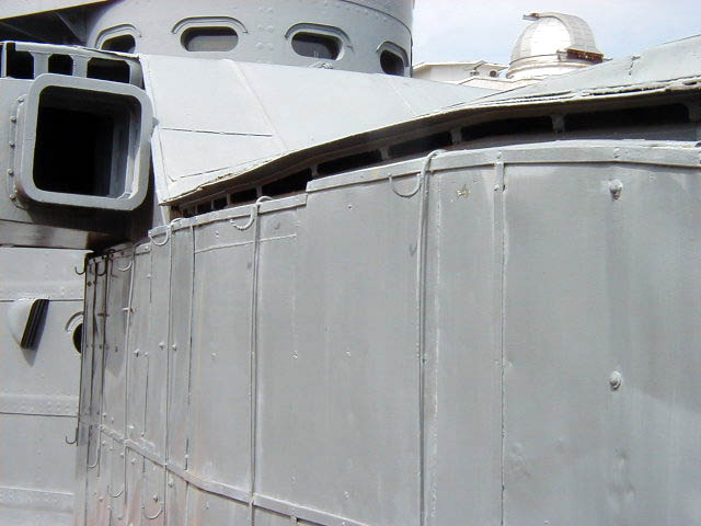
- ^The Kosaku Ariga (Jarek) website was discontinued in 2010. At that website, there were many photographs of a Japanese-built 20 cm (7.9") twin mounting used on the Thailand Coastal Defense ship HTMS Thonburi. Jarek sent these to me some years ago for review and I have now added these photographs below. On his website, Jarek described this mounting as being either a Model D mounting similar to those on the Myôkô class or as a Model B mounting removed from the carrier Kaga. From my examination of these photographs and others, I believe that the first of these statements is correct. The turret used on Thonburi shows the same sloped-roof and super-imposed rangefinder typical of the earlier twin mountings such as the Model D used on the Myôkô class. The Model B used on Kaga (and the very similiar Model E used on later cruisers) had flat roofs with the rangefinder partially enclosed within the mounting. I believe that the guns in the Thailand mounting are the 20 cm (7.9") 3rd Year Type No. 1 guns, as the chase shows a tapering after the "C" tube that does not appear in photographs of the 20 cm (8") 3rd Year Type No. 2 guns used on Japanese heavy cruisers during World War II. As a guess, the guns used for the Thonburi class could have been among those removed from Japanese cruisers when they were upgraded to the larger 20 cm (8") 3rd Year Type No. 2 guns. The gunhouses themselves may have been originally built as spares for the Myôkô class.
- ^The maximum elevation of the Model B was +70 degrees, but the elevating and recoil mechanisms proved to be fragile and it was found that +55 degrees was the maximum practical elevation.
- ^The elevation of the single guns used on Akagi and Kaga was restricted to 20-23 degrees for much of their training arc in order to avoid blast damage. These guns were mounted low in the ships and were of limited use.
- Model C and Model D twin turrets had a crew of 19 in the gunhouse, nine in the shell room and ten more in the powder magazine. Model B had additional crewmen due to their additional pair of shell hoists with a crew of 23 in the gunhouse and more in the shell rooms.
- The twin mount gun axes were 74.8 in (190 cm) apart.
- All Models had only splinter protection consisting of 25.4 mm (1") of NVNC steel plates on all sides except the bottom, which was protected by 19 mm (0.75") thick plates.
- The gunhouses for Models B, C and D mountings had thin steel sheeting along the top and sides to provide a 10 cm (3.9") air space around the turrets. This sheeting provided shading for tropical service.
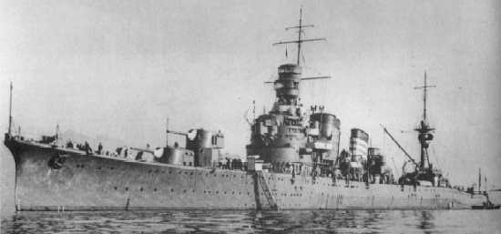
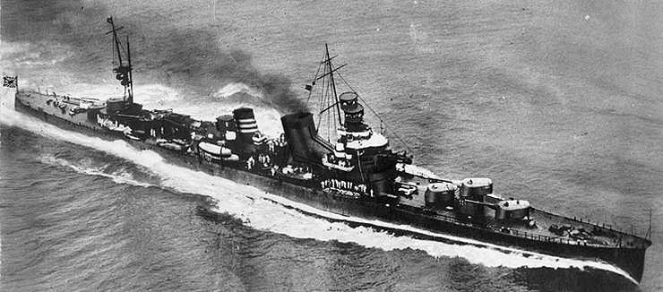
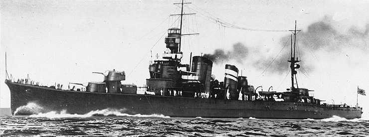


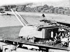
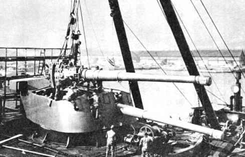
These pictures were taken on 15 December 2001 at the Thai Naval Academy at Paknam, Bankok, Thailand. Photographs copyrighted by Vidya Tapasanan and used here by permission of Kosaku Ariga (Jarek).
The name of this Thai warship is sometimes transliterated as "Dhonburi," but recent information from the Royal Thai Navy (RTN) says that "Thonburi" is correct.
Model D Type turret with 20 cm/50 (7.9") 3rd Year Type guns.
The mechanisms on the gun ports are for supporting bloomers and are typical of other Japanese turret designs.
Internal views of Thonburi turret
"Naval Weapons of World War Two" by John Campbell
"Ships of the World, Volume 57" by Kohji Ishiwata, Editor
"Japanese Naval Vessels Illustrated 1869-1945, Volume 3, Aircraft Carriers" by Kojinsha, Editor
"Japanese Cruisers of the Pacific War" by Eric Lacroix and Linton Wells II
"Cruisers of World War Two" by M.J. Whitley
---
"Survey of Japanese Seacoast Artillery" by U.S. Army Forces, Pacific - Proceedings of a Board of Officers dated 27 October 1945
---
Special help from Kosaku Ariga (Jarek)
19 April 2007 - Benchmark
25 December 2011 - Added HTMS Dhonburi Page
07 January 2012 - Additional mounting information and changed note about Kosaku Ariga (Jarek) website
01 September 2012 - Added information on projectiles and mountings
15 October 2012 - Added overhead view of Kako
17 October 2012 - Minor changes for clarity
15 May 2017 - Converted to HTML 5 format
01 April 2019 - Reorganized notes
30 April 2020 - Minor correction
30 April 2022 - Reorganized note for Thailand ships
04 October 2022 - Replaced "Dhonburi" with "Thonburi" per Royal Thai Navy information
28 October 2023 - Added note about restricted gun elevation, use on carriers and comment on breech mechanism


