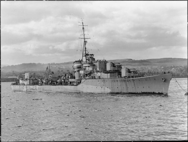
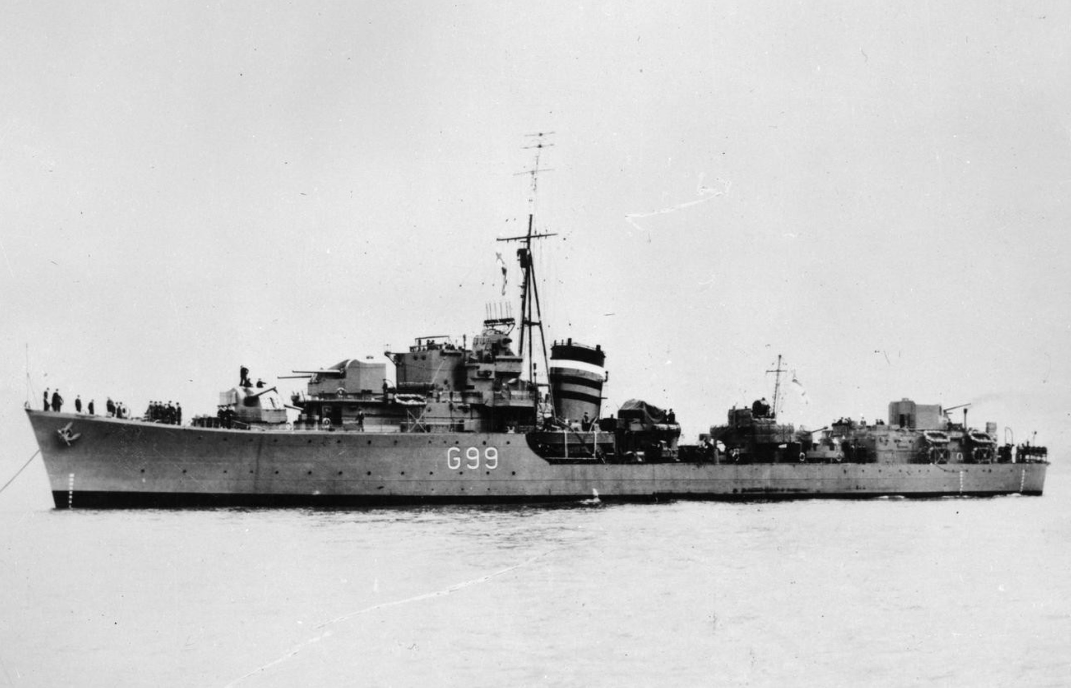
By 1938, the Admiralty recognized that British destroyers compared badly with their USA and Japanese counterparts, as they were lacking DP main guns and weather-proof mounts. The 4.7"/50 (12 cm) Mark XI guns and Mark XX twin mounting were intended to correct these deficiencies. These guns fired a heavier shell of more modern design and their mountings allowed higher elevations than did most other British guns of this caliber. However, their slow training rate and manually operated elevation gear limited their usefulness in the AA role and for that reason many of these destroyers had the after torpedo mounting replaced during World War II with a single 4" (10.2 cm) Mark V HA gun.
In my opinion, this was Britain's best destroyer gun of World War II for surface action, although its low maximum elevation and slow training and elevation speeds made it only marginally useful for anti-aircraft defense. Unfortunately, the cost and size of these destroyers was so much greater than the previous designs that only a few were built and newer destroyers reverted to a smaller size and were armed with the cheaper 4.7"/45 (12 cm) guns.
The guns were in separate sleeves and could not be coupled together. The mountings used hydraulic systems for training, ramming and shell hoists. They were quite complicated, which resulted in long production delays and caused four of the L class destroyers to be completed with four twin 4" (10.2 cm) Mark XIX mounts in place of the three 4.7" (12 cm) mounts.
There was some thought given in 1938 to developing a hand-worked single mounting using the 4.7"/50 (12 cm) gun. This would have been used to arm the first of the War Emergency destroyers (O and P classes). Development of this design was slow and instead these destroyers were armed with old 4"/45 (10.2 cm) Mark V and 4.7"/45 (12 cm) Mark IX guns.
In 1958 four "M" class destroyers were sold to Turkey and then extensively refitted. One of the modifications was to add power elevation, thus correcting one of the major deficiencies of this mounting.
Constructed of autofretted loose barrel, jacket to 85 inches (216 cm) from the muzzle, removable breech ring and sealing collar. Used a manually operated breech mechanism with semi-automatic breech opening. A total of 87 guns were manufactured.
Actual bore diameter of all British 4.7" guns was 4.724" (12 cm).
| Designation | 4.7"/50 (12 cm) QF Mark XI |
|---|---|
| Ship Class Used On | L and M Classes |
| Date Of Design | about 1938 |
| Date In Service | 1940 |
| Gun Weight | 3.351 tons (3,405 kg) |
| Gun Length oa | 247.7 in (6.292 m) |
| Bore Length | 236.2 in (6.000 m) |
| Rifling Length | 204.9 in (5.204 m) |
| Grooves | (38) 0.0365 in deep x 0.270 (0.927 x 6.86 mm) |
| Lands | 0.1205 in (3.061 mm) |
| Twist | Uniform RH 1 in 30 |
| Chamber Volume | 670 in3 (10.98 dm3) |
| Rate Of Fire | 6 - 10 rounds per minute 1 |
- ^The firing cycle was nominally 6 seconds but large angles of train made loading more difficult and increased the cycle time.
| Type | Separate |
|---|---|
| Projectile Types and Weights 1a | HE - 62 lbs. (28.12 kg)
SAP - 62 lbs. (28.12 kg) |
| Bursting Charge | N/A |
| Projectile Length | N/A |
| Propellant Charge | 12.81 lbs. SC or 15.38 lbs. NF/S (5.81 or 7.0 kg) | Cartridge Case Type, Size and Empty Weight | Brass, 120 x 716.2 R mm, about 19.4 lbs. (8.8 kg) |
| Muzzle Velocity | 2,538 fps (774 mps) |
| Working Pressure | 20.5 tons/in2 (3,230 kg/cm2) |
| Approximate Barrel Life | 800 rounds |
| Ammunition stowage per gun | 250 rounds 2a |
- ^This was the only weapon of this caliber to fire projectiles of modern design with 5/10crh heads and heavier weight.
- ^Outfits included 150 SAP, 100 HE, 25 LA practice and 16 HA practice per gun plus 50 star shells for B mounting. Sixty special anti-submarine HE shells with RDX/TNT fillers were supplied to each ship by 1945 and the star shell allotment was increased to 150 - 200 rounds per ship.
| Designation | Twin Mounting
L (3) and M (3): CP Mark XX |
|---|---|
| Weight | Gunhouse including guns: 84,217 lbs. (38,200 kg)
Including mount base and hoists: 128,089 lbs. (58,100 kg) |
| Elevation | -10 / +50 degrees |
| Elevation Rate | Manually operated, only 1b |
| Train | about +150 / -150 degrees |
| Train Rate | 10 degrees per second |
| Gun recoil | 26.5 in (67.3 cm) |
| Loading Angle | Any |
- ^The widely separated gun barrels meant that the guns had to be individually sleeved and thus dual elevation mechanisms were needed. As built, these were manually operated, as the extra weight involved ruled out power drives. Power elevation was fitted to the four "M" class destroyers sold to Turkey in 1958. I lack the elevation rate for these modified mountings.
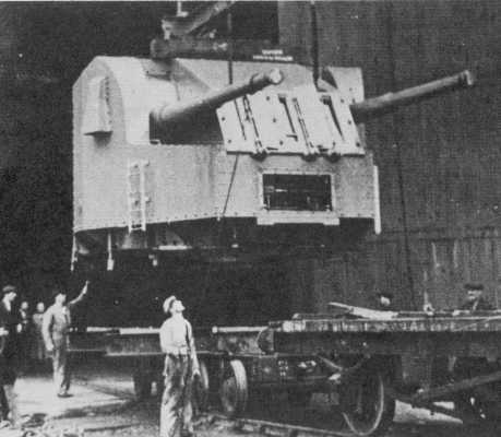
- Intended to save costs, an unusual feature of this mounting was that only the gunhouse rotated, the ammunition supply hoists did not rotate and were part of the fixed structure. This design necessitated that the ammunition and powder hoists needed to come up at the center of rotation, which explains why the guns are so widely separated in this mounting. Since the hoists did not rotate with the mounting, large angles of train caused difficulties with transferring ammunition to the guns and thus slowed down the ROF. "Destroyer Weapons of World War 2" notes that a true turret mounting including a rotating stalk would have almost certainly been rejected by the Exchequer for cost reasons. However, given the actual cost growth experienced during design and construction, one must wonder if the final cost of such a true turret mounting would have been much if any different from the final design. It almost certainly would have meant a smaller gunhouse and lower mounting weight and thus a smaller destroyer overall.
- The gun axes were 96 in (244 cm) apart. How astonishingly wide this is may be appreciated by noting that the gun axes for the 15"/42 (38.1 cm) Mark II twin mounting used on HMS Hood were only two inches (5.1 cm) wider. The gun axes for the concurrent 4.7"/45 (12 cm) Mark CPXIX twin mounting used on other British destroyers were considerably narrower at 38 in (96.5 cm).
- The mountings were each powered by a 45 bhp (peak 102 bhp) electric motor and oil hydraulic pump on the fixed structure. Training was by a single hydraulic motor with two worm and pinion drives. Run out was powered by compressed air. Each gun had its own shell hoist and charge hoist. Shells and cartridges were placed by hand on the tilting tray of the fuze setter and then slid to the loading tray. The loading tray contained both the hydraulic and the manual rammers and was rotated by hand. Shell and cartridge were rammed together at any angle of elevation.
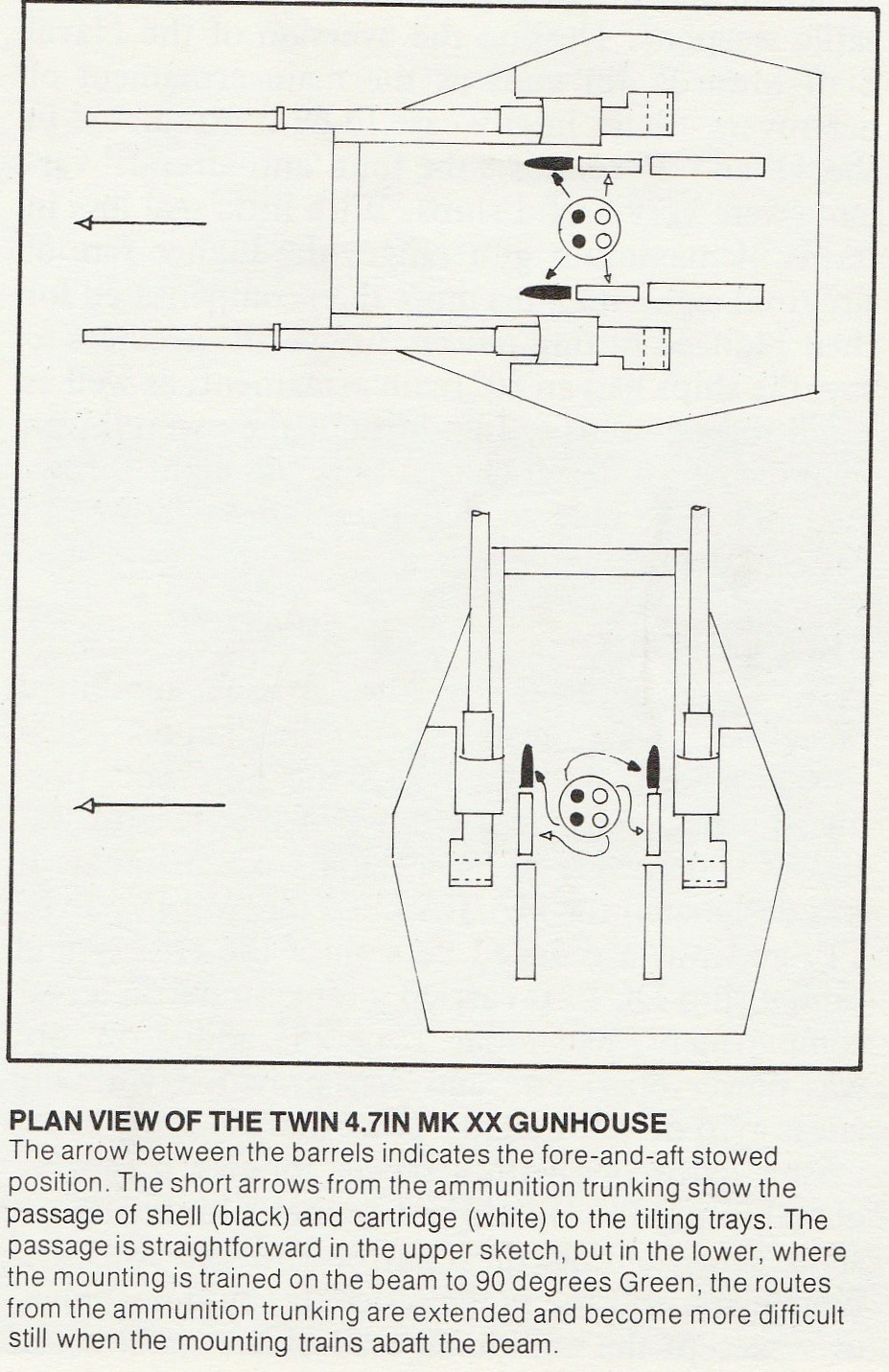

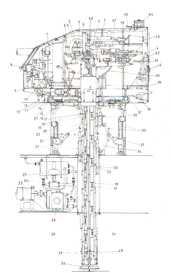
Sketch by John Lambert and used here by his kind permission. Image from "Naval Weapons of World War Two" by John Campbell.
| 1. Fuze receiver | 25. Motor |
| 2. Shell hoist control lever | 26. Pump |
| 3. Fuze setting machine | 27. Operating cylinder for shell hoist |
| 4. Ready use shells | 28. Shell room |
| 5. Tilting tray | 29. Shell hoist loading tray |
| 6. Trunnion bracket | 30. Drip tray |
| 7. Cordite hoist control lever | 31. Magazine |
| 8. Training receiver | 32. Operating cylinder for cordite hoist |
| 9. Training cut off gear | 33. Cordite hoist |
| 10. Hand and power lever | 34. Air cylinder |
| 11. Training clutch gear box | 35. Hand operated cordite hoist |
| 12. Training buffer stop | 36. Air blast |
| 13. Upper roller path | 37. Turntable clip |
| 14. Roller | 38. Training housing stop |
| 15. Lower roller path | 39. Elevating arc |
| 16. Training motor | 40. Teleflex indicator |
| 17. Shell hoist | 41. Gun loading tray |
| 18. Fixed pawl | 42. Lookout platform |
| 19. Moving pawl | 43. Balance weight |
| 20. Moving pawl POD | 44. Lookout hood |
| 21. Clutch lever - hand and power | 45. Safety trainer's sight |
| 22. Hand operated shell hoist | 46. Intensifier |
| 23. Oil tank | 47. Recuperator |
| 24. Strainer | 48. Cordite hoist loading tray |
Images at The Vickers Photographic Archive
See Mark XX Mounting
"Nelson to Vanguard: Warship Design and Development 1923-1945" and "The Design and Construction of British Warships 1939-1945: Major Surface Warships" both by D.K. Brown
"Naval Weapons of World War Two" and "British Naval Guns 1880-1945 No 15" article in "Warship Volume IX" both by John Campbell
"Destroyer Weapons of World War 2" by Peter Hodges and Norman Friedman
"Destroyers at War" by Gregory Haines
"French Destroyers: Torpilleurs d'Escadre & Contre-Torpilleurs 1922 - 1956" by John Jordan and Jean Moulin
"Okrety Rzeczpospolitej Polskiej 1920-1946" ("Warships of Republic of Poland 1920-1946") by Stanislaw M. Piaskowski
"British Battleships of World War Two" by Alan Raven and John Roberts
"Milne" article in "Warship Volume III" by John Roberts
"Destroyers of World War Two" by M.J. Whitley
---
Special help from Andrzej Sluzek
05 March 2007 - Benchmark
30 January 2009 - Added link, construction information and ammunition stowage and outfit quantities
09 September 2011 - Added mounting notes
24 November 2012 - Corrected typographical errors
09 August 2014 - Added photograph of HMS Loyal
15 August 2014 - Redid sketch
14 September 2015 - Added breech view photograph
01 December 2015 - Changed Vickers Photographic Archive links to point at Wayback Archive
14 February 2017 - Converted to HTML 5 format
06 August 2020 - Reorganized notes
03 November 2021 - Minor changes in ammunition section, changed photograph of HMS Laforey
04 March 2022 - Changed appearance of sketch by John Lambert
