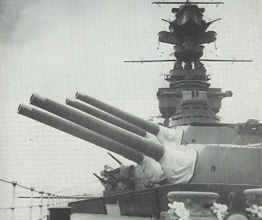
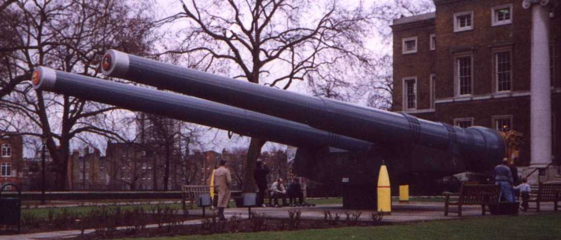
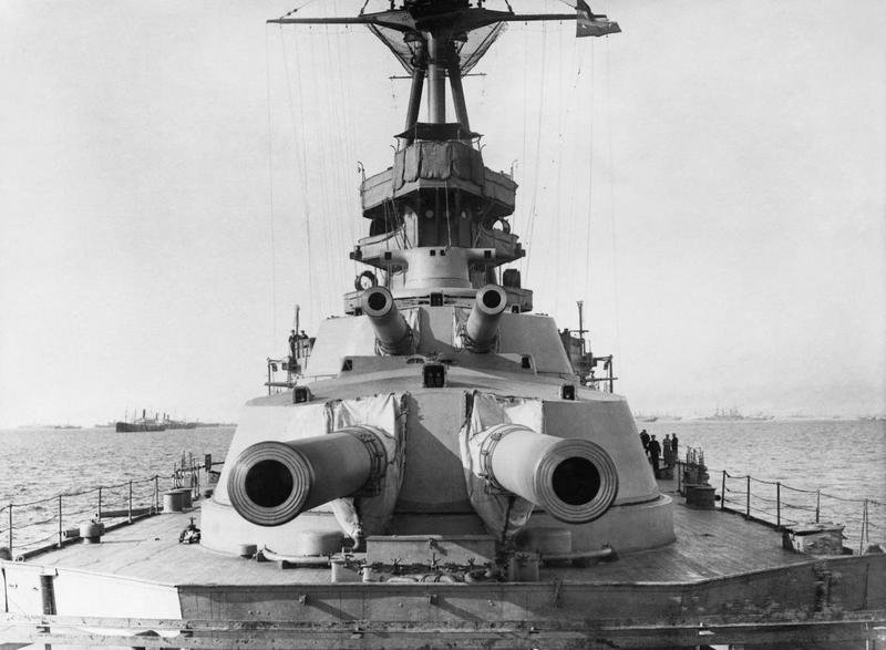
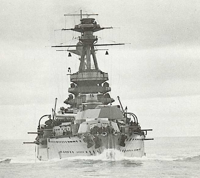
This was quite possibly the best large-caliber naval gun ever developed by Britain and it was certainly one of the longest-lived of any nation, with the first ship-board firing taking place in 1915 and the last in 1954. The design of this weapon was largely based upon the 13.5"/45 (34.3 cm) Mark V and it was rushed into production, bypassing the normal - and lengthy - prototype stage. This shortened design cycle was approved by the Director of Naval Ordnance, Rear Admiral Archibald Moore, who staked his "professional existence" on its success. The reason for this rushed procedure was to allow what became the Queen Elizabeth class battleships to be armed with larger guns than would have otherwise been possible. Although their first warshots were for bombarding shore positions at Gallipoli in 1915, the value of these weapons was not truly shown until the Battle of Jutland (Skagerrak). In that battle, the British battleships with these guns were able to engage German battlecruisers at a range of 19,000 yards (17,400 m), which was beyond the maximum range of the guns on the German ships.
By the mid-1930s the Admiralty saw these guns as growing obsolete, as other nations had developed more powerful weapons, capable of longer ranges and firing heavier projectiles. Along with this, the ships carrying these guns were approaching twenty years of service and starting to show signs of wearing out. Inhibited by treaty restrictions from replacing the battleships, the British instead sought to rectify the situation by initiating a "modernization" program whereby the ships had major overhauls performed and had their weapons upgraded. There were two significant improvements made to these guns during the modernizations: 1) The upper elevation limit of the mountings was increased from 20 degrees up to 30 degrees, which raised their maximum range with 4crh projectiles from 23,700 yards up to 29,000 yards (21,670 m to 26,520 m), and 2) The projectiles were improved and a more streamlined ballistic cap (6crh) was fitted which increased their range still further to about 32,000 yards (29,260 m) at 30 degrees elevation. Thanks to these modifications, in July 1940 HMS Warspite made one of the longest hits ever scored by a naval gun on an enemy ship when she struck the Italian battleship Guilio Cesare at approximately 26,000 yards (23,770 m).
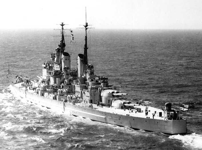
The rate at which these ships could be modernized was limited and by the start of World War II Malaya, Barham, Repulse and the five Royal Sovereign class battleships had not yet been upgraded. Royal Oak, Barham and Repulse were sunk early in the war, but the remaining unmodernized ships were given a "Super Charge" which consisted of the largest possible propellant charge that the guns and mountings could safely handle. These were issued starting in late 1941 and at the maximum elevation of 20 degrees allowed a range of 28,700 yards (26,240 m). However, from a study of the records, it would appear that no ship ever fired a shot using Super Charges, although they were used by the coastal artillery at Dover. Super Charges were not issued to ships with 30 degree mountings as the increased barrel wear and mounting stress was not considered to be acceptable. For this reason, sources which quote HMS Vanguard as having gun ranges in excess of 32,000 yards (29,260 m) are somewhat misleading, as such a range would have required the use of super charges, which she never carried.
In addition to the ship-board guns, there were also five guns used as coastal artillery at Singapore and a further two mounted at Wanstone near Dover. After the war ended in 1945, these last two guns were maintained in an operational state and were not removed until 1959.
Constructed of tapered inner A tube, A tube, full-length multi-start wire, B tube, overlapping jacket and breech ring. Used a Welin breech operated by hydraulic Vickers "pure-coupled" mechanism. A total of 186 guns, including two prototypes, and 58 turrets were manufactured between 1912 and 1918.
The second prototype gun, E597, was to a considerably different construction, having a full-length jacket, no B tube and an Elswick three-motion short arm breech mechanism which considerably reduced "slam." This gun suffered a failed A tube during proof testing. Had this gun not failed, the Elswick breech mechanism probably would have been used on all production guns.
Note: It is often asked if the British ever planned to use these guns for the King George V battleships of World War II. The answer is that they did not, but there was some investigation into using a new design, the "all steel" 15"/45 (38.1 cm) Mark II gun.
| Designation | 15-inch Mark I |
|---|---|
| Ship Class Used On | Battleships: Queen Elizabeth, Royal Sovereign and Vanguard classes
Battlecruisers: Glorious, Repulse and Hood ("Admiral") classes Monitors: Marshal Soult, Erebus and Roberts classes |
| Date Of Design | 1912 |
| Date In Service | 1915 |
| Gun Weight | 224,000 lbs. (101,605 kg) including breech mechanism |
| Gun Length oa | 650.4 in (16.520 m) |
| Bore Length | 630.0 in (16.002 m) 42 calibers |
| Rifling Length | 516.3 in (13.115 m) |
| Grooves | (76) 0.1245 in D x 0.445 in W (2.16 x 11.30 mm) |
| Lands | 0.175 in (4.445 mm) |
| Twist | Uniform RH 1 in 30 |
| Chamber Volume | 30,650 in3 (502.3 dm3) |
| Rate Of Fire | 2 rounds per minute 1 |
- ^The nominal firing cycle for the Mark I and Mark I* mountings was 36 seconds, but 30.2 seconds was achieved on 1 October 1917 by one ship. The Mark II mountings used on Hood had a nominal firing cycle of 32 seconds.
The following excerpt is taken from "Progress in Gunnery Material, 1921" ADM 186/251:
32. Comparison between British and German Gun Designs(a) The design of German 38 cm, 42.4 calibre Naval gun mounted in “Baden” has been carefully investigated and compared with that of the British 15 in. Mark I 42 calibre gun.
(b) The main points of difference between this [German] design and British designs are as follows:
(i) The gun is not relinable.(ii) Factors of safety are lower. In calculating the strength of the gun at any point, the Germans allow the steel to be stressed much nearer to its elastic limit that we do in our designs, also the figure of elastic limit which they take for purposes of calculation is higher than ours. The gun is not serviceable with barrel split.
(iii) The gun is a Q.F., which permits of radical differences in construction from those necessary at the breech end of a B.L. gun.
(iv) All-steel construction as against wired type.
(v) Much smaller chamber (Capacity 18,000 cu. in. as compared to our 30,590.)
[Comments on the above items](c) As regards (i), the life of our guns (about 325 E.F.C.) is apparently considerably less than that of German heavy guns owing to their use of cooler propellant. They evidently considered that the life of their guns was long enough to justify the simpler lighter design which is possible when relining is not intended. Experiments with propellants generally similar to the German are in hand, but some time must elapse before any can be adopted to replace cordite M.D. in the Service. Until then it is considered that we should certainly continue to design our guns for relining.The effect generally of (i), (ii) and (v) is to lighten the gun considerably.(iii) is a matter of general policy ; there are reasons both for and against Q.F. guns of this calibre
(iv) The advantages of all-steel versus wire-wound guns have been the subject of discussion for a great many years, and opinions still differ as to which is better than the other from point of view of strength and ballistics ; more recently, however, it has been considered probable that the smaller droop and greater rigidity of the all-steel type may be a very important factor in effect on accuracy. The German gun is noticeably stiff in the region of the centre of gravity, making for small droop and whip ; this is undoubtedly a good point.
(d) As regards (ii), apparently German designers placed greater reliance on their steel forgings than we do on ours, and consequently stressed them much more highly. In all large steel forgings there is always a certain factor of uncertainty which we have allowed for and the Germans have been content to neglect. This is not confined to gun construction, but it is to be found throughout British engineering practice generally. The high factors of safety used in this country are considered to be partly due to the above and partly to caution, which may have been brought about by a few failures of guns in the past caused by faulty building or poor steel, also because there has been no special demand for light gun. We now call for a factor of safety of 1.5 over the chamber and of 2 forward before the steel is stressed up to a figure well below the specification yield point (20 tons as against the German 27). Consequently according to German ideas our factor of safety is 2 or 2.7.
The possibility of reducing the factors of safety in our gun designs has been the subject of discussion recently, and trials to test whether they are unduly great have been arranged for. Doubtless some reduction will now be possible in view of the great advance in machining operations and steel treatment made of late years, but improvements materially affecting our designs can only be adopted gradually. It is confidently anticipated that the forgings for the 16 in. designs will be much superior to what we have had in the past and fully equal to the German, the chief advance being in improvement in elastic limit and resistance to shock, which latter as evidently been specially attended to by German steel makers and is now provided for in our specifications for steel forgings.
The effect of these two points (lower factor of safety and high stress in the steel in the German design) is very marked over the chase with consequent reduction in weight and therefore decrease in the droop – a point already referred to in para. (b).
(e) As regards (iii), a movement between breech bush and inner tubes in a Q.F. gun with cartridge case is of much less importance than with B.L. gun and obturator pad in maintaining an effective seal, and this has permitted the longitudinal stresses being taken direct by the jacket, the breech bush screwing into this instead of into the A tube as in our designs. This simplifies design and manufacture. It has also permitted the use of short hoops in lieu of a long B tube, a form of construction that offers many advantages in accuracy of building shrinkage, though at the same time providing less longitudinal strength, which is poor in the German design according to our ideas.
The fact that the Germans accepted this longitudinal weakness shows that they had great confidence in the workmanship and skill of their gunmakers, as good results depended entirely on these. Our guns are undoubtedly easier to build and are so strong circumferentially due to the wire that the accuracy in building shrinkages, necessary in the German design[,] has not been called for.
(f) As regards (iv), steel and wire construction will be tried out in the trial 16 in. designs, also in trial 6 in. guns to be manufactured this year.
(g) As regards (v), the small size of chamber is not suitable for a solid cord propellant which we have hitherto adhered to. The question of adopting a tubular propellant [may be resolved as] various experiments are in progress.
The opinion is now held that the tubular shape makes for higher M.V. but reduced accuracy as regards mean differences in M.V.
It is more difficult to manufacture to accurate dimensions than cord or oval. Also, with a propellant such as M.D. cordite which has a volatile solvent (acetone) there would be less uniformity of stick than is obtainable with a propellant (like the German) with non-volatile solvent. Ardeer cordite 1a has a non-volatile solvent. Again, owing to its form, a tubular propellant is inherently more susceptible to the influence of variations in ballistic conditions, and thus, though actual wear may be less, loss of velocity for a fewer number of rounds may be greater.
It is, however, one of the many things that requires further investigation before we can be in a position to decide finally what to adopt in the future. It is quite certain that we shall be able to improve on cordite M.D.
(h) Apparently the Germans consider it unnecessary to fire proof rounds in testing guns for supply, and, to take this gun as an example, this certainly permitted them to cut down factors of safety, and therefore weight.
(i) Summarising, the main lessons to be learnt from study of the German design are :-
(i) The possibility of reduced factors of safety being introduced into our designs, especially towards the muzzle.(ii) The reduction of droop by (i) combined by the use of all-steel construction with a view to obtaining greater rigidity and consequently improved accuracy. At the same time distance of centre of gravity of gun from breech end would probably be decreased, and this would be advantageous as affecting diameter of barbette and size of mounting generally.
(iii) The need for taking advantage of manufacturing progress and greater knowledge obtained by experience in ordering trial guns of new designs from time to time, so that when new guns are required in supply they can be ordered to the most up-to-date designs. Unless this is done, our gun designers cannot acquire confidence in their designs nor can the gun makers gain experience in building.
(iv) The necessity for constantly revising our specifications to obtain the best possible gun steel, and for ensuring by strict inspection during manufacture, that specifications are adhered to and that the workmanship is of the highest standard.
The trial 16 in. guns and experiments in hand on other guns will test some of these points, but the trial guns have chases with a large factor of safety and the droop is therefore not the smallest obtainable.
(j) It may be of interest to mention here that the trial 16 in. gun under manufacture by E.O.C. weighs practically the same as a gun of similar calibre that has been designed working to German figures and methods. It will be clear, therefore, that a good deal has been done already towards reducing weight ; but, although this is very desirable, it can certainly be overdone, and if the gun is not sufficiently stiff, its accuracy will be less good than one where weight has been subordinated all through to gunnery considerations. There is no doubt at all as to the importance of stiffness in a gun.
(k) It is the intention to build, next year, a 6 in. gun to the German design, so far as this can be done without adopting the Q.F. principle, and to try this gun against our guns of similar calibre.
- ^"Ardeer" was a large cordite factory located in Ayrshire, Scotland and was involved in the development of new propellants following World War I. For some interesting historical information, please see The Great Dynamite Factory.
| Type | Bag |
|---|---|
| Projectile Types and Weights 1b | World War I era
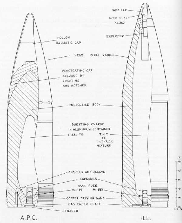
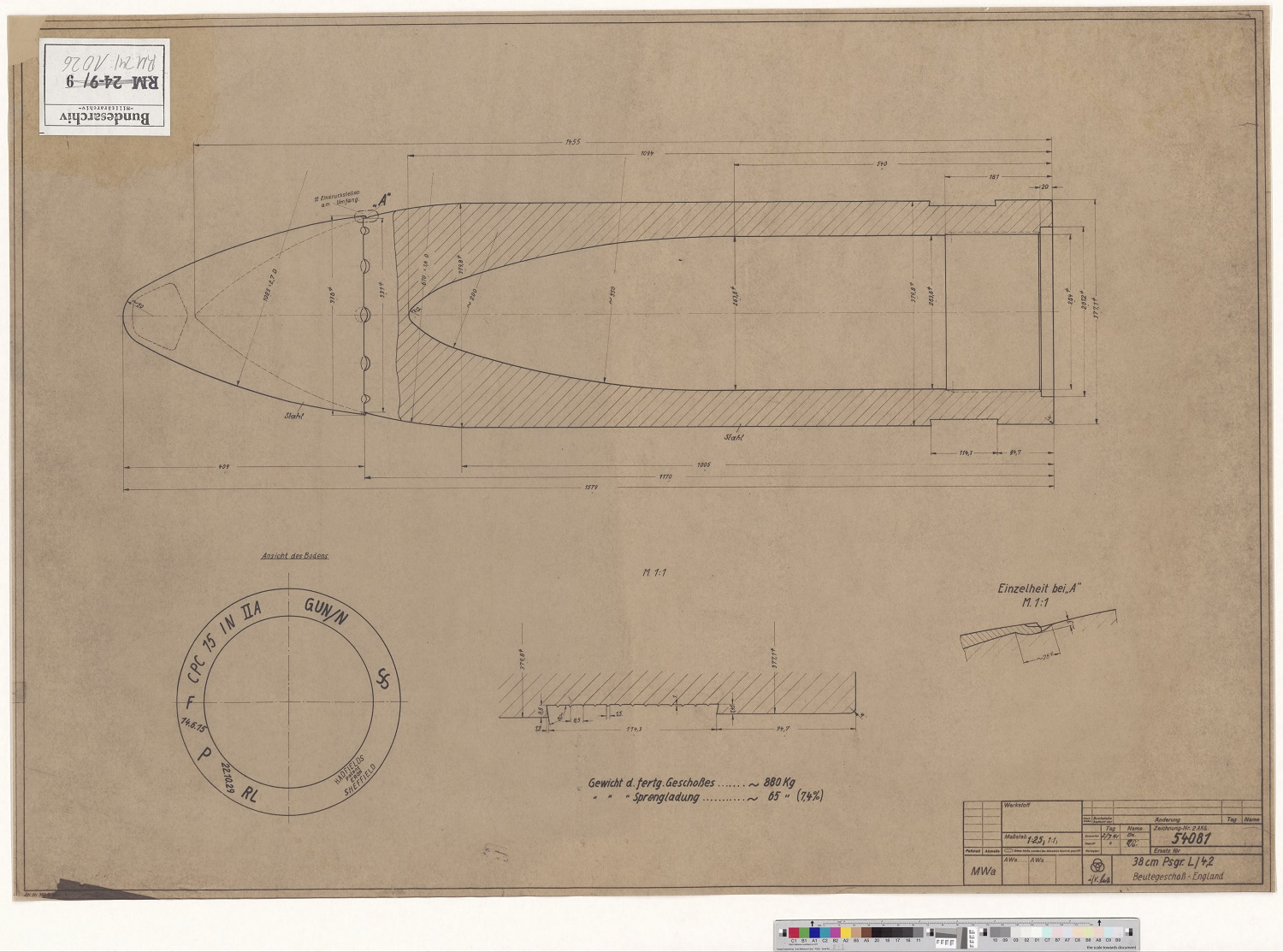
APC Mark Ia (4crh): 1,920 lbs. (871 kg) APC Mark IIIa (4crh - Greenboy): 1,910 lbs. (866.4 kg) APC Mark Va (4crh - post World War I): 1,917 lbs. (869.5 kg) 2b APC Mark VIIa (4crh - post World War I): 1,917 lbs. (869.5 kg CPC 4crh: 1,920 lbs. (871 kg) HE Mark VIa (4crh): 1,920 lbs. (871 kg) HE 8crh: 1,965 lbs. (891 kg) 3b Shrapnel 4crh: 1,920 lbs. (871 kg) Inter-war to World War II era
4b |
| Bursting Charge 7b | World War I era
APC Mark Ia: 60.5 lbs. (27.4 kg) Lyddite APC Mark IIIa: 45.3 lbs. (20.5 kg) Shellite APC Mark Va: 45.3 lbs. (20.5 kg) Shellite APC Mark VIIa: 45.3 lbs. (20.5 kg) Shellite CPC: 129.3 lbs. (58.6 kg) Originally Black Powder, later TNT HE, Mark Unknown: 216.5 lbs. (98.2 kg) TNT HE Mark VIa: 162.0 lbs. (73.5 kg) Shellite HE 8crh: 224.0 lbs. (101.6 kg) Lyddite Shrapnel: 13,700 lead-alloy balls of 1.75 oz (49.6 gm) each Inter-war to World War II era
|
| Projectile Length | World War I era
APC Mark Ia: 54.5 in (138.4 cm) APC Mark IIIa: 55.9 in (142.0 cm) APC Mark Va: 55.9 in (142.0 cm) APC Mark VIIa: 55.9 in (142.0 cm) CPC: 63.3 in (160.8 cm) HE 4crh: 63.9 in (162.3 cm) HE 8crh: about 75 in (190 cm) 3b Shrapnel: about 63.9 in (162.3 cm) Inter-war to World War II era
|
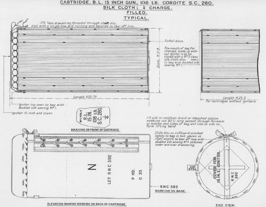
| Propellant Charge 8b | World War I: 428 lbs. (194 kg) MD45
After 1927 (standard charge): 432 lbs. (196 kg) SC 280 9b Super charge: 490 lbs. (222.2 kg) SC 300 |
| Muzzle Velocity 10b | World War I era
APC 4crh: 2,467 fps (752 mps) Inter-war to World War II era
|
| Working Pressure | MD and SC standard charge: 20 tons/in2 (3,150 kg/cm2)
Super Charge: 23 tons/in2 (3,620 kg/cm2) |
| Approximate Barrel Life | 335 rounds 11b |
| Ammunition stowage per gun 12b | Queen Elizabeth, Royal Sovereign and Vanguard 13b classes: 100 rounds 14b Renown, Courageous and Hood classes: 120 rounds Marshall Soult and Erebus: 100 rounds Abercrombie and Roberts: 110 rounds |
- ^The 4crh projectiles are more properly defined as 3.05/4crh. The 6crh projectiles are more properly defined as 5/10crh. See the Naval History and Technology essay, Calculating crh for further information.
- ^Comments by Sven Brummack based upon his research of ADM 186/169 and ADM 186/259:
It seems that the 15 in (38.1 cm) Mark Va projectile became the new standard around ca. 1920 (Hadfield started making them in early 1919). The lot numbers given for all but one of the APC used in the Baden Trials 2nd series (see below) imply that these projectiles were either Mark Va or Mark VIIa (not sure when Mark VIIa were proofed and how they exactly differed from Mark Va) and not the original Greenboy projectiles (Mark IIa and Mark IIIa). The only APC projectile not given with lot number in the 2nd series is round No. 14, and this round is also identified as a Hadfield Mark Va. The differences in these projectiles is not a minor quibble. The period between 1918-1921 saw a vast improvement in British A.P. projectile technology, with major successes achieved in multiple areas converging to provide the fleet with a reliable delay action fuze equipped, armor piercing projectile. A lot of effort was spent to raise the proof limit from 8 in (20.3 cm) at 20 degrees angle of obliquity to 10 in (25.4 cm), aiming at raising it to 12 in (30.5 cm) at 20 degrees. The original 15 in (38.1 cm) Mark IIa and Mark IIIa "Greenboy" shells, at least initially, were sometimes not quite as successful in meeting the new 10 in (25.4 cm) at 20 degrees proof specification. So that the inferior shells would not be wasted, they could be approved to a somewhat lower specification and then designated as APC 'X' if they penetrated a plate 8 in (20.3 cm) thick or as APC 'R' if they passed the prescribed tests after multiple retests. All these sub-quality Greenboys were issued to the battlecruiser force in the spring and early summer of 1918 on account of the assumed lower thickness of German battlecruiser armor. Projectiles that passed the new requirement - i.e. 10 in (25.4 cm) at 20 degrees - and projectiles which passed the raised proof specification - i.e. 12 in (30.5 cm) at 20 degrees - were issued to the Grand Fleet on account of the need to provide for an effective projectile against the thickest armored German opponents. Projectiles from lots which passed the raised proof specification of 12 in (30.5 cm) at 20 degrees were specially designated as "superproof" / "blue band" and eventually became the new service standard shortly after World War I, roughly at the time of the Baden trials. 'X' and 'R' shells were replaced by the new Mark Va shells during 1919/20. Unless one assumes that the 1st series Baden Trials used older shells that were no longer in service (even "Greenboy" 'X' and 'R'-shells were replaced soon after the end of hostilities), an assumption which is not supported either by circumstantial evidence or by statements relating the APC projectiles used in the 1st and 2nd series of Baden Trials, I consider it a reasonable presumption to assume that all APC used in the Trials were to the same standard, which was the Mark Va during this period. This is founded upon the success the British had in maturing A.P. projectile technology in this period. Late Greenboys (15 in (38.1 cm) Mark Va) and early Greenboys (15 in (38.1 cm) Marks IIa and IIIa) differed significantly in their ability to negotiate oblique impact in a condition fit to burst and this was reflected by the differences in proof specification. In a document dated 1922, I assume that the statement "APC now delivered to the fleet" reflects the latest proof specification, which conforms in the lot numbers and proof dates of the 2nd series APC.
- ^3.13.2The 8crh projectiles were only supplied to Monitors and were introduced in 1918. These had the same shell body as the standard 4crh HE projectiles but had a longer ballistic cap which gave them an additional 3,000 yards (2,730 m) of range over the 4crh HE projectiles. As a guess, the 8crh projectiles would have been at least 75 inches (190 cm) long.
- ^The 6crh projectile family was introduced in 1938. Originally, these new projectiles were limited to Warspite, Renown, Valiant and Queen Elizabeth. In other words, they were only issued to those ships with the upgraded Mark I/N or Mark I*/N mountings. This was apparently because the projectile handling equipment on the non-modernized ships could not accommodate the longer 6crh shell. Those ships that did not get this handling system upgrade (including HMS Hood) could not use these longer shells, so in their place they were given projectiles with the same shell body and cap but fitted with a shorter 4crh windscreen similar to the older APC Mark Va -- the shells were heavier due to a thicker AP cap and a blunter pointed nose under it (1.3crh), but they were the same length as the earlier Mark Va shells. Following a refit in mid-1940, HMS Barham was outfitted with 6crh projectiles and the surviving ships were modified to use them from late-1941 to mid-1943. Hood, Royal Oak and Repulse apparently never carried 6crh projectiles, as they were all sunk before the necessary modifications could take place.
- ^According to Nathan Okun, all of the 15" (38.1 cm) APC shells in use during World War II had similar armor penetration performance with the exception of the special limited-issue APC Mark XVIIb shells developed by and manufactured by Cardonald of Scotland. These had a markedly superior penetration ability due to their harder nose and more rigid middle body. Confusingly, these shells did not get their own Mark number designation, meaning that there were other shells in service with the Mark XVIIb designation that did not have the better penetration capability.
- ^During World War II "K" shell Mark Ib NT was introduced which contained dyes for coloring the shell splashes. These shells also had a small fuze and burster to disperse the dye. These additions increased the APC shell weight. Active ships had the following colors listed in a 20 June 1946 Fleet Order:
Queen Elizabeth: Red
Valiant: Green
Vanguard: Yellow
Renown: None (White) - ^The well-known failure of British APC to penetrate German armor at Jutland (Skagerrak) was partly due to the sensitive nature of the Lyddite bursters which caused many shells to explode immediately following impact on the target. In the next few years a new burster called "Shellite" was developed which was a mixture of Lyddite and dinitrophenol (DNP), which was a much weaker and insensitive explosive. Originally, a mixture of 50/50 was used, but this gave insufficient fragmentation. Tests with 60% Lyddite and 40% DNP bursters were satisfactory, and it was this combination that was used for the first "Greenboy" APC projectiles issued beginning in 1918. Soon after the end of the war, it was determined that a 70/30 mixture would give improved fragmentation while maintaining an adequate margin against premature detonations. This mixture was used for all subsequent British APC projectiles of this caliber.
- ^Propellant was in quarters for all charge types. Super charges were supplied at the rate of twenty per gun to ships with a maximum gun elevation of 20 degrees.
- ^Range Table temperature for SC 280 propellant was 70 degrees F. The temperature correction per 10 degrees F (6 degrees C) change was 10 fps (3.0 mps).
- ^A Note on Sources: There are disagreements between the sources listed below as to the muzzle velocity of these guns, which I suspect has to do with whether they use "new gun" or "average gun" figures. In the table above, I have chosen to use those muzzle velocity figure given in "Warship Volume V" for MD charges, the muzzle velocity figures given in "B.R. 980 (D)" for standard SC charges and the muzzle velocity figure for SC super charges given in "Naval Weapons of World War Two." These are "new gun" figures, while the muzzle velocities given in the range tables below are "average gun" figures and are taken from official British range tables.
- ^The life figure given here is for APC fired with full charges. Life with Super Charges was estimated as equivalent to two EFC. HE was limited to 250 EFC as the longer body and greater longitudinal inertia could result in unsteady flight if the rifling was too worn. Erosion was greatly affected by the size of the charge, with a 3/4 charge causing only 1/4 of the erosion of a full charge. The 15" (38.1 cm) guns were usually condemned when the wear reached about 0.74" (1.9 cm) at a point one inch (2.54 cm) from the start of the rifling. Guns in otherwise good condition could be relined by replacing the inner A tube.
- ^Outfits for all battleships and the Renown class were originally limited to APC as it was intended that they only fight capital ships. The Renown class later carried 60 APC and 60 CPC, then 72 APC, 24 CPC and 24 HE and at the end of the war they carried 84 APC and 36 CPC per gun. The Courageous class were originally designed for 80 rounds per gun but this was increased to 120 rounds following the Falklands battle, where ammunition expenditure was very heavy. The Courageous class initially carried 72 APC, 24 CPC and 24 HE, but all HE was replaced with CPC by mid-1917 and the immediate post-war outfit was 36 APC and 84 CPC per gun. The Royal Sovereign class may have carried 104 rounds per gun as commissioned. In the 1920s, 6 shrapnel rounds per gun were added to most battleships while the outfit for the Renown class was changed to 96 APC, 24 CPC and 6 shrapnel rounds per gun plus a total of 70 practice rounds. As completed, Hood had an outfit of 289 CPC, 672 APC, 30 shrapnel (stored only in the bow shell rooms) and 82 practice rounds. After her 1929-1931 refit, her outfit was changed 160 CPC (TNT burster), 640 APC (Shellite burster), 48 shrapnel and 96 practice rounds, saving about 200 tons (203 mt) on an overweight ship. The three follow-on "Admiral" class battlecruisers would have had their outfits reduced to 110 rounds per gun for "A" and "B" turrets and to 100 rounds for "X" and "Y" turrets due to the reversal of the placement of the magazines and shell rooms - see the Mount / Turret Notes below for additional information. In the latter years of World War II, surviving ships replaced five APC rounds per gun with HE unless they were assigned to bombardment missions, in which case the proportion of HE was greatly increased. Outfits for monitors during World War I was 10 CPC (for use against fortified positions) and 90 HE per gun while during World War II it was 30 to 60 APC or CPC and the balance HE. Monitors usually carried 8 practice shells per gun. HMS Vanguard when commissioned carried 95 APC, 5 HE and 9 practice shells per gun.
- ^After her conversion to "Royal Yacht" in 1947, HMS Vanguard rarely carried any main gun ammunition at all and little secondary or AA ammunition, as she had become badly overloaded. "X" turret was put into a state of preservation and was never made functional again while "Y" turret was rendered inoperable in order to allow the use of a sunroom on the after deck. In 1951 Vanguard was tasked as the Home Fleet flagship but she had become primarily a peacetime status symbol. In 1952 the Gunnery Division of the Naval Staff estimated that it would take seven months to get her operational as a warship again. Main armament shoots were seldom performed during this time and those that were conducted used just the forward turrets and are said to have been primarily intended as morale boosters rather than for serious gunnery training. "HMS Vanguard was a pleasant and spacious flagship, but a Naval Staff anxious to increase her combat efficiency seemed faced with a choice between filling an overweight ship with ammunition or with fuel should she actually ever be made into a fully combatant unit." - Eric Grove in "Vanguard to Trident." In 1955, Vanguard was decommissioned for a refit and weight reduction program which was intended to make three of her four turrets operational and allow them to carry their full outfit of 15 inch (38.1 cm) shells for the first time since 1946. Half of her secondary and AA armament was also to be made functional during this refit. However, this program was halted in March of 1956 and she was then placed in reserve. She was sent to the scrapyard in 1960.
- ^After modernizations during the 1930s, Queen Elizabeth, Valiant and Warspite carried 106 rounds per gun.
- At the start of World War I, a CPC projectile cost about £65, HE £37 and a full charge £40. These prices had almost doubled by the start of World War II.
- The USA firm of Crucible Steel supplied some APC and HE projectiles during World War II. Trials with the APC shells showed that their armor penetration was about equal to the ones manufactured by Hadfield and Firth Brown although inferior to the ones made by Cardonald. During firing missions at the Normandy Invasion beaches on 06 June 1944, the monitors HMS Erebus and HMS Roberts each had one gun destroyed by bore prematures which were traced to faulty fuzes in the HE rounds made by Crucible Steel.
| Elevation | Range | Striking Velocity | Time of Flight | Angle of Fall |
|---|---|---|---|---|
| 1.0 degrees | 1,920 yards (1,756 m) | --- | --- | 1.0 |
| 2.6 degrees | 5,000 yards (4,570 m) | 2,074 fps (632 mps) | --- | 3.0 degrees |
| 5.0 degrees | 8,629 yards (7,980 m) | --- | --- | 6.0 degrees |
| 5.9 degrees | 10,000 yards (9,140 m) | 1,776 fps (541 mps) | 14.6 seconds | 7.3 degrees |
| 10.0 degrees | 14,853 yards (13,582 m) | --- | --- | 13.0 degrees |
| 10.1 degrees | 15,000 yards (13,720 m) | 1,537 fps (468 mps) | --- | 13.6 degrees |
| 15.0 degrees | 19,707 yards (18,020 m) | --- | --- | 21.0 degrees |
| 15.6 degrees | 20,000 yards (18,290 m) | 1,377 fps (420 mps) | 35.1 seconds | 22.3 degrees |
| 20.0 degrees 3c | 23,734 yards (21,702 m) | --- | --- | 29.0 degrees |
| 20.0 degrees 3c | 23,387 yards (21,385 m) | --- | --- | --- |
| 22.5 degrees | 25,000 yards (22,860 m) | 1,317 fps (401 mps) | 48.7 seconds | 32.7 degrees |
| 30.1 degrees | 29,000 yards (26,520 m) | 1,326 fps (404 mps) | 62.1 seconds | 42.0 degrees |
- ^Data from "The Big Gun."
- ^In this table, elevations above 20 degrees apply only to HMS Hood and to the monitors, as these were the only ships as completed that had gun elevations greater than 20 degrees. Ships given extensive modernizations in the 1930s had their mountings modified to achieve 30 degree elevations, but those ships were then issued 6crh projectiles.
- ^3.13.2A Note on Sources: For reasons that are not made clear in the text of "The Big Gun," two different ranges for 20 degree elevation are given for 1,920 lbs. (871 kg) 4crh shells. The first value shown here is presented as part of a table of figures and appears to be from the range tables for this weapon. There is no indication as to what the second figure represents, but I include it here for reference purposes.
- I lack range information for the APC Mark XIIa and APC Mark XIIIa (6crh projectiles with 4crh ballistic caps issued to unmodernized ships during World War II). As these were ballistically similar to the older 4crh projectiles but slightly heavier, I would assume that their ranges would be a few percentage points longer than the older 4crh projectiles.
- 8crh projectiles were used only by Monitors and only during World War I. These gave a maximum range of about 32,000 yards (29,260 m) at an elevation of 30 degrees.
| Elevation | Range | Striking Velocity | Time of Flight | Angle of Fall | Maximum Ordinate |
|---|---|---|---|---|---|
| 2.6 degrees | 5,000 yards (4,570 m) | 2,144 fps (653 mps) | 6.58 seconds | 2.7 degrees | 160 feet (48 m) |
| 5.6 degrees | 10,000 yards (9,140 m) | 1,909 fps (582 mps) | 14.11 seconds | 6.6 degrees | 800 feet (244 m) |
| 9.3 degrees | 15,000 yards (13,720 m) | 1,709 fps (521 mps) | 22.64 seconds | 11.7 degrees | 2,060 feet (628 m) |
| 13.8 degrees | 20,000 yards (18,290 m) | 1,556 fps (474 mps) | 32.52 seconds | 18.3 degrees | 4,230 feet (1,289 m) |
| 19.2 degrees | 25,000 yards (22,860 m) | 1,461 fps (445 mps) | 43.80 seconds | 26.3 degrees | 7,790 feet (2,374 m) |
| 26.1 degrees | 30,000 yards (27,430 m) | 1,433 fps (437 mps) | 57.28 seconds | 35.6 degrees | 13,350 feet (470 m) |
| 30.5 degrees | 32,500 yards (29,720 m) | 1,446 fps (441 mps) | 65.41 seconds | 40.7 degrees | 17,340 feet (5,285 m) |
- ^Data from B.R. 980 (D).
- ^Due to its heavier weight, the average gun muzzle velocity for the APC Mark 1b NT projectile was 3 fps (1 mps) less than the 1,938 lbs. (879 kg) 6crh projectiles.
| Elevation | Range | Striking Velocity | Time of Flight | Angle of Fall | Maximum Ordinate |
|---|---|---|---|---|---|
| 2.2 degrees | 5,000 yards (4,570 m) | 6.15 seconds | 2,312 fps (705 mps) | 2.4 degrees | 150 feet (46 m) |
| 4.9 degrees | 10,000 yards (9,140 m) | 13.06 seconds | 2,063 fps (629 mps) | 5.7 degrees | 670 feet (204 m) |
| 8.0 degrees | 15,000 yards (13,720 m) | 20.91 seconds | 1,852 fps (564 mps) | 10.0 degrees | 1,730 feet (527 m) |
| 11.7 degrees | 20,000 yards (18,290 m) | 29.79 seconds | 1,683 fps (513 mps) | 15.5 degrees | 3,590 feet (1,094 m) |
| 16.1 degrees | 25,000 yards (22,860 m) | 39.68 seconds | 1,560 fps (475 mps) | 22.2 degrees | 6,400 feet (1,951 m) |
| 20.0 degrees | 28,800 yards (26,335 m) | 48.40 seconds | 1,506 fps (459 mps) | 28.0 degrees | about 9,456 feet (2,882 m) |
| 21.4 degrees | 30,000 yards (27,430 m) | 51.27 seconds | 1,497 fps (456 mps) | 29.9 degrees | 10,620 feet (3,237 m) |
| 27.9 degrees | 35,000 yards (32,000 m) | 64.59 seconds | 1,496 fps (456 mps) | 38.3 degrees | 16,860 feet (5,139 m) |
| 30.3 degrees | 36,500 yards (33,380 m) | 69.20 seconds | 1,507 fps (459 mps) | 40.9 degrees | 19,330 feet (5,892 m) |
| 44.6 degrees | 42,000 yards (38,400 m) | 95.50 seconds | 1,634 fps (498 mps) | 53.9 degrees | 36,800 feet (11,217 m) |
| Range | Side Armor | Deck Armor |
|---|---|---|
| 8,629 yards (7,980 m) | 16.0" (406 mm) | --- |
| 14,853 yards (13,582 m) | 12.0" (305 mm) | --- |
| 19,707 yards (18,020 m) | 11.0" (279 mm) | --- |
| 23,734 yards (21,702 m) | 9.0" (229 mm) | --- |
This data is from "The Big Gun" and refers to World War I-era armor plate and probably refers to APC of the early World War I era, not the later, improved "Greenboy" projectiles. This table assumes 90 degree inclination, i.e., an angle of obliquity of 0 degrees. It should be noted that APC of this time did not reliably penetrate at even modest angles of obliquity and were subject to premature bursting, so these values should be used with caution.
| Range | Side Armor | Striking Velocity | Angle of Obliquity |
|---|---|---|---|
| 0 yards (0 m) | 18.0" (457 mm) | 2,450 fps (869 mps) | 0 |
| 10,000 yards (9,144 m) | 14.0" (356 mm) | 1,850 fps (579 mps) | 0 |
| 10,000 yards (9,144 m) | 13.2" (335 mm) | 1,850 fps (579 mps) | 20 |
| 10,000 yards (9,144 m) | 12.2" (310 mm) | 1,850 fps (579 mps) | 30 |
This data is from "British Battleships of World War Two" for uncapped AP shells against KC Plate armor of World War I and probably refers to armor piercing projectiles of the early World War I era, not the later, improved "Greenboy" projectiles. The first two rows are for a projectile striking a plate at an angle of 0 degrees, i.e., with the axis of the shell perpendicular to the face of the plate. The next two rows are for shells striking at larger angles and show the degradation in penetration performance for the same striking velocity as the angle increases. A capped shell (APC) would show about 10 to 20% improvement at low velocities and about 30 to 50% improvement at high velocities.
| Range | Side Armor | Deck Armor |
|---|---|---|
| 17,200 yards (15,730 m) | 14.0" (356 mm) | --- |
| 18,000 yards (16,460 m) | --- | 2.0" (51 mm) |
| 19,400 yards (17,740 m) | 13.0" (330 mm) | --- |
| 21,700 yards (19,840 m) | 12.0" (305 mm) | --- |
| 24,000 yards (21,950 m) | --- | 3.0" (76 mm) |
| 24,500 yards (22,400 m) | 11.0" (279 mm) | --- |
| 28,000 yards (25,600 m) | 10.0" (254 mm) | 4.0" (102 mm) |
| 29,500 yards (26,970 m) | --- | 5.0" (127 mm) |
| 32,500 yards (29,720 m) 1f | --- | 6.0" (152 mm) |
- ^Note that the range necessary to penetrate 6.0" (152 mm) of deck armor is at or beyond the maximum range of guns firing SC standard charges at an elevation of 30 degrees.
- This data is from "British Battleships of World War Two." This table assumes 90 degree inclination and is based upon theoretical calculations performed in 1935, not actual firing trials.
| Range | Side Armor | Deck Armor |
|---|---|---|
| 0 yards (0 m) | 27.1" (687 mm) | --- |
| 10,000 yards (9,144 m) | 16.5" (422 mm) | 1.25" (32 mm) |
| 15,000 yards (13,716 m) | 13.9" (353 mm) | 1.95" (50 mm) |
| 20,000 yards (18,288 m) | 11.7" (297 mm) | 3.10" (72 mm) |
| 25,000 yards (22,860 m) | 10.2" (259 mm) | 4.30" (121 mm) |
| 30,000 yards (27,432 m) | 9.0" (229 mm) | 5.70" (145 mm) |
This data is from "Battleships: Allied Battleships in World War II" for a muzzle velocity of 2,400 fps 732 mps) and is partly based upon the USN Empirical Formula for Armor Penetration and partly based upon official data.
In 1921 the British conducted a series of gunnery trials using the last battleship completed by the Germans during World War I, the surrendered Baden. These trials were conducted as a part of the design process for the next generation of capital ships, which were later cancelled as a result of the Washington Naval Limitation Treaty. During these gunnery trials, the monitors Erebus and Terror fired a total of 31 shells using reduced charges in order to obtain striking velocities equivalent to the expected battle ranges. Two primary striking velocities were used, 1,550 fps (472 mps) simulating a range of 15,500 yards (14,170 m) and 1,380 fps (421 mps) simulating a range of 21,800 yards (19,930 m).
Tests at 1,550 fps (472 mps) with 4crh "Greenboy" APC showed that these projectiles could penetrate turret face armor of 35 cm (13.8 in) when struck at an angle of 18.5 degrees and penetrate barbette armor of 35 cm (13.8 in) when struck at an angle of 11 degrees, but that this same armor thickness on the conning tower successfully defeated an APC striking at an angle of 30 degrees. Another test at this velocity saw an APC striking at an angle of 14.5 degrees penetrating the upper armor belt of 25 cm (10 in) and this shell then traveling some 38 feet (11.6 m) before bursting on the funnel casing and damaging two boilers, having first penetrated a 3 cm (1.2 in) splinter bulkhead and the 1.2 cm (0.5 in) main deck.
Five rounds of APC were fired at 1,550 fps (472 mps) at the 10 cm (3.9 in) turret roof armor, with four of these failing to penetrate.
Tests at 1,380 fps (421 mps) with CPC projectiles showed that armor of 17 cm (6.75 in) could be penetrated, but that these shells could neither penetrate nor significantly damage the 35 cm (13.8 in) barbette armor when striking at a 12 degree angle.
There is a cautionary note in ADM 186/251 that may apply to these trials:
Unsteadiness of shells at plate proof - When firing shells with reduced charges to obtain the required S.V. [striking velocity] for the proof or trial of shells or armour, particularly with the larger natures, there is a tendency for shells to be unsteady in flight, as shown by the shape of the hole made in a jump card erected in front of the armour plate. This unsteadiness tends to vitiate the result of the trial. As each round at thick armour may cost as much as £2,000 or more, it is a serious matter to reject the evidence of a round and to repeat it on the score of unsteadiness, although this has sometimes to be done.The Admiralty's overall conclusion from these trials was that the new "Greenboy" APC projectiles had satisfactory penetration characteristics, although their fuzing was not considered successful. Neither the experimental SAPC nor the older CPC used in these trials was considered to be effective. The penetration of the SAPC was disappointing and showed no advantage over APC. The CPC projectiles had considerable blast effect, but the fragments created by their thin walls were too small to cause significant damage.
Data in this section is primarily from "Washington's Cherrytrees: The Evolution of the British 1921-22 Capital Ships" articles by John Campbell, from excerpts of ADM 186/251 provided to me and from "The Baden Trials" article by William Schleihauf.
| Designation | Capital Ship Two-gun Turrets
Queen Elizabeth (4) and Royal Sovereign [except Resolution] (4): Mark I Resolution (2) Mark I and (2) Mark I* 1g Repulse (2) Mark I and (1) Mark I* Renown (3), Courageous (2) and Glorious (2): Mark I* Hood (4): Mark II 2g Rebuilt Mountings 3g Monitor Two-gun Turrets 5g |
|---|---|
| Weight 6g | Mark I and Mark I*: 770 tons (782 mt)
Mark II: 880 tons (894 mt) Mark I/N: 815 tons (828 mt) Mark I/N RP 12: 855 tons (869 mt) |
| Elevation | Mark I and Mark I*: -5 / +20 degrees
Modified Mark I and Modified Mark I*: +2 / +30 degrees Mark II: -5 / +30 degrees Mark I/N, Mark I*/N and Mark I/N RP 12: -4.5 / +30 degrees Coastal artillery: -3 / +50 or +55 degrees |
| Rate of Elevation | 5 degrees per second |
| Train 7g 8g | -150 / +150 degrees |
| Rate of Train | 2 degrees per second |
| Gun Recoil 9g | 46 in (117 cm) |
| Loading Angle 5g 10g | Marks I, I* and II: -5 to +20 degrees
Marks I/N and I*/N: -4.5 to +20 degrees Monitors except Abercrombie: +5 degrees |
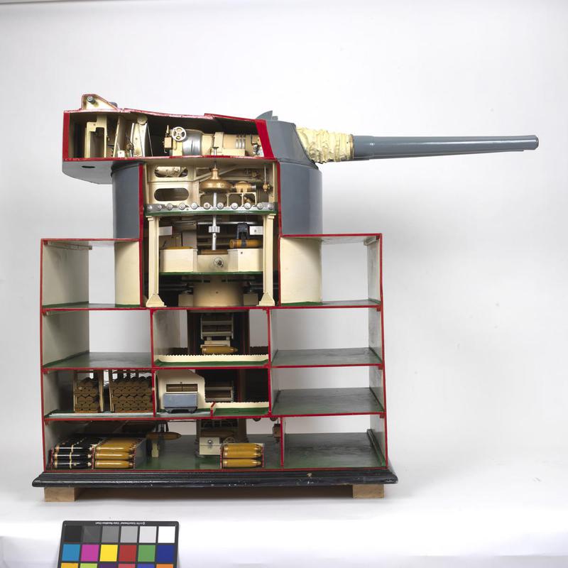
- ^The Mark I* differed from the Mark I in that Kenyon Doors were used in place of the shell bogies, otherwise the basic design was the same. The use of thinner armor in the battlecruiser turrets gave them circular front plates while the battleship turrets had polygon shaped front plates. As built, the battleship turrets had 15 foot (4.57 m) MG8 rangefinders that were contained entirely within the gunhouse. Later, 30 foot (9.17 m) MG14 rangefinders were fitted to the rear of "B" and "X" turrets on the battleships and to "B" turret only on the battlecruisers Renown and Repulse. The twin turret mountings each sat on 48 rollers and were hydraulically powered from a ring main using a water/soluble oil mixture. Elevation was by hydraulic cylinder connected to the slide. Each gun was served by two ammunition cages, one for the projectile and one for the propellant. These were loaded separately but then hoisted together to the gunhouse. Cost of a Mark I mounting was £116,000 for the mounting and an additional £32,000 for the two guns.
- ^The Mark II mount was used only on HMS Hood and had a polygon shaped front plate similar in shape to the battleship turrets. The Mark II turret itself was considerably taller than the Mark I to allow for the increased gun elevations. Besides the increased elevation, the Mark II turrets differed from the Mark I by having thicker armor and as follows: All four turrets had 30 foot (9.17 m) MG14 rangefinders; improved flash-tightness added to the handling room cordite hoppers and to the cordite hoist cage; a flash door added to the hoist well; a forced lubrication system for the worm shaft of the training gear; adjustable anti-surging stops fitted to the shell cage to allow different shell lengths and to stop shells from moving in a seaway; sighting hoods on gunhouse roof replaced by sighting ports in the turret face; armored officer's cabinet and; hydraulic run-out for the guns replaced by pneumatic run-out. The near-sisters of HMS Hood, the follow-on "Admiral" class battlecruisers, had many design changes before being finally cancelled shortly after the war ended. One of these changes was to give their turrets a more rectangular shape with increased protection. These new turrets probably would have been designated as Mark III had these ships been completed.
- ^During modernizations carried out in the 1930s, Queen Elizabeth, Valiant, Warspite and Renown had their turrets lifted off the ship and sent to the Vickers-Armstrong ordnance works at Elswick for modifications to increase the maximum elevation from 20 degrees up to 30 degrees. Besides altering the elevation machinery, this was accomplished by enlarging the gun ports, raising the slide trunnions 8.75 in (22.2 cm) and moving them back 7.25 in (18.4 cm). The guns and slides were moved forward relative to the trunnions by the same amount. This change gave the necessary clearance in the gun wells but the gunloading cage rails had to be moved forward in order to reach the new breech position. There was a penalty in that a 12 ton (12.2 mt) balance weight had to be fitted to the rear collar of each gun. The elevation cylinders and elevation walking pipes also had to be redesigned to accommodate these positional changes and pneumatic run-out was fitted to eliminate the "stalling" problem at higher elevations. Sighting hoods were removed and sighting ports were added in their place, which increased the practical firing arcs. Flashtightness was improved and there were many minor improvements were made. Modified mountings can be easily identified by the "hooded" armor fittings used to cover the larger gun port openings. These modified Mark I and Mark I* turrets were redesignated as Mark I/N and Mark I*/N, respectively.
- ^The 15" (38.1 cm) Mark I* mountings used on HMS Vanguard were actually old ones removed from the British Battlecruisers (or "Unorthodox Cruisers") HMS Glorious and HMS Courageous which had been placed into storage when these ships were converted into aircraft carriers. While Vanguard was being constructed, these mountings were greatly modified to bring them up to more modern standards and increase armor protection. In general, those modifications listed above in Note 3g - including increasing the maximum elevation from 20 degrees up to 30 degrees - were performed along with alterations to the cordite hoppers on the trunk to improve flashtightness. Armor protection was improved as follows:
- The 8.8" (22.4 cm) (360 lbs.) glacis plates were replaced by 12.74 in (32.4 cm) (520 lbs.) FH plates.
- The 4.16" (10.6 cm) (170 lbs.) roof plates were replaced by 5.88" (14.9 cm) (240 lbs.) NC plates.
- The 1.95" (5.0 cm) (80 lbs.) floor plates were replaced by 2.9" (7.5 cm) (120 lbs.) NC plates. This alteration to the floor plates was intended to better balance the new armor additions rather than to improve protection.
A significant new addition was having remote power control (RPC) equipment for training fitted - RPC for elevation was not fitted. HMS Vanguard was the only British battleship to have RPC installed for both main and secondary armaments. The increased elevation for the main armament required cutting larger gun port openings in the turret faceplates. To compensate for these larger openings, armored hoods were fitted over the gun ports, similar to the Mark I*/N mountings. In addition, 24.5 foot (7.47 m) FX stabilized rangefinders - not 30 foot (9.17 m) rangefinders as stated in many references - were installed on the rear of "B", "X" and "Y" turrets. The corresponding space in "A" turret was used as a secondary conning position. To increase magazine protection, Vanguard's magazines were relocated below the shell rooms, which was the reverse of the arrangement used for all other British capital ships with 15" (38.1 cm) guns, but was similar to the design used for the 14" (35.6 cm) mountings on the King George V class. To accommodate this change, the turret trunks now ended at the shell handling rooms and the magazine handling rooms were located above them. The magazines were connected to the handling rooms by fixed hoists, three each for turrets "X" and "Y" and four each for turrets "A" and "B". Something else to note about these mountings is that all four were from ships that did not have superfiring turrets. So, the two mounts destined for Vanguard's "B" and "X" positions had to be substantially reworked in order for them to be used in those superfiring positions. The support structures for all four mountings were stiffened to take the greater recoil forces involved when using supercharges, but as noted above, supercharges were never issued to this or any other ship with mountings capable of 30 degree elevation. Finally, de-humidifying equipment and lagging was fitted to the gunhouse to improve habitability. Vanguard's mountings were now designated as Mark I/N RP 12 (some sources say Mark I*/N RP 12, as the turrets were originally designated as Mark I*, but I believe this to be incorrect). It should be noted that it was only the mountings themselves that came from the battlecruisers, the guns used to arm HMS Vanguard actually came from the reserve stock of spare units. - ^5.15.2The mountings for the monitors Marshal Soult and Marshal Ney had their slide trunnions raised 25.5 in (64.8 cm) in order to allow +2 / +30 elevation (please note, these guns could not depress to the horizon). Other changes involved more powerful elevation machinery, enlarging the gun ports and covering them with 0.5 in (1.27 cm) thick armored hoods and changing to fixed-angle loading. The monitors Roberts and Terror reused the mountings removed from Marshal Soult and Marshal Ney, respectively. The monitor Erebus used one of the two 15" (38.1 cm) Mark I* turrets originally built for HMS Furious in case the 18"/40 (45.7 cm) Mark I guns were unsuccessful. This was modified in a similar manner as the mountings for the other monitors to allow +2 / +30 elevation. All of these Monitors had a fixed loading angle of +5 degrees. The monitor HMS Abercrombie was given the other HMS Furious Mark I* mounting, but this was more heavily modified to the Mark I*/N standard. In addition, the trunk was shortened by about 7.5 feet (2.3 m), the Kenyon doors were replaced by shell bogies, a shell handling room was built with shells transferred from the shell room via four rammer trays and flashtight scuttles were added to the hoppers on the main trunk in the magazine handling room. The flash doors on the gun loading cage were also redesigned.
- ^A Note on Sources: There is disagreement between the sources listed below as to the revolving weight of these mountings. I have chosen to use those figures given in "Naval Weapons of World War Two."
- ^With the exceptions of HMS Hood and HMS Vanguard, superfiring turrets on these ships as built could not fire within 30 degrees of the axis because the blast effects would have penetrated into the lower turrets through the open sighting hoods. The four ships given major rebuilds during the 1930s replaced these hoods with sighting ports and so could now fire on the axis if necessary. From an examination of photographs taken during World War II, it would appear that this problem was not corrected on the unmodernized ships. As an example of this, in 1944 the non-reconstructed HMS Malaya mounted 20 mm Oerlikon AA guns atop "A" turret which were thus located directly below the muzzles of "B" turret, which implies that she could not fire "B" turret on a forward bearing.
- ^Peter Elvin, who in 1942 was appointed as the first full-time damage control officer aboard HMS Renown, reported that the "15-inch gun training hydraulic engines" did not work at list angles "far less than the designed failure angle." During damage control exercises, he was able to quickly heel Renown to a 10 degree list "in just a few minutes" and lists of 14 degrees could be obtained by bulge flooding and "a bit of cross-pumping of liquids." Although he does not specifically so state, the described main-armament training problems may have occurred at these larger list angles. Renown at this time had rebuilt Mark I*/N mountings. However, HMS Resolution was torpedoed in September 1940 and took up a 12 degree list after which time her turrets could not be trained. Resolution had not been upgraded as was Renown and was still armed with her original Mark I and Mark I* mountings.
- ^The recoil distance given here is the nominal figure. The absolute, metal-to-metal recoil distance was 47.25 inches (120 cm).
- ^In the original mounting design, the chain rammer was carried on an extension to the slide which theoretically allowed loading to be performed over a large range of elevation, -5 to +20 degrees. However, it was found during World War I that the hydraulic system lacked enough capacity to both run the guns out at high elevations and handle all of the other hydraulic loads. This situation resulted in the mounts "stalling" during gun run-out, greatly slowing the loading cycle. A further problem was that the driving band on the projectiles would not always "bite" into the rifling during ramming. At the higher elevations this failure allowed the projectiles to slide back out of the breech when the rammer was withdrawn, which must have been a fairly "exciting" occurrence. For these reasons, loading was generally performed at +5 degrees or less. Turrets modernized during the 1930s had the run-out problem fixed by switching to pneumatic runout, but may still have suffered from the projectiles sliding out of the breech at higher elevations. Cordite was rammed two bags at a time.
- With the exception of Vanguard, none of these ships were ever fitted with RPC equipment, they continued to use "follow the pointer" gear throughout their careers. Vanguard was fitted with RPC for training, while elevation remained "follow the pointer."
- A typical crew consisted of 64 men: In the gunhouse and handling room there were the turret captain, the second captain, two gunlayers, one trainer, three sight-setters, six loading crew for each gun and then five control and communications men. In the magazine were 19 crewmen and 19 more in the shell room. Finally, each turret had an ordnance artificer.
- Flash protection was increased on all ships after the Jutland (Skagerrak) battle.
- As part of the studies for new capital ships following World War I, the monitor HMS Lord Clive was used for experiments with triple mountings to test for shell interference problems. She had her 18"/40 (45.7 cm) Mark I and secondary guns removed in 1920 and was then fitted with three 15"/42 (38.1 cm) guns in a fixed broadside mount, firing to starboard. During firing trials in March 1921, one of these guns suffered a bore premature from a faulty, "old type" APC projectile. This burst the jacket and wrecked the gun, slightly injuring one crewman. Other than that disruption, the trials were successfully conducted and concluded that there were no serious shell interference problems for a triple mount.
- The 250 foot (76 m) Radio Telescope at Jodrell Bank, Chesire, England, used elevation gear salvaged from the Mark I mountings on the battleships HMS Royal Sovereign and HMS Revenge.
- A Note on Sources: "The Big Gun" states that the gun axes for the Mark I and Mark I* were both 90 in (228.6 cm) apart while "Naval Weapons of World War Two" lists them at 98 in (249 cm) apart. I believe that 98 in (228.6 cm) to be correct based upon measurements made on photographs of Mark I mountings. Both of these references and others state that the gun axes on the Mark II were 98 in (249 cm) apart.
- Typical manning of a 15" (38.1 cm) mounting was 64 officers and men, broken down as follows:
Gunhouse - 17
Working Chamber - 6
Magazine - 12
Handling Room - 7
Shell Room - 22 - The three follow-on "Admiral" class battlecruisers were to have their magazines located below their shell rooms, the first British dreadnoughts so configured. This change was the result of testing in the Chatham float which had shown that if a mine exploded beneath the magazine then water would flood in quickly enough to give a good chance of preventing the magazine from exploding. This arrangement was used in all subsequent British capital ship designs.
- Armor thickness given in "Naval Weapons of World War Two" and "British Battleships of World War Two":
Except as denoted below, the Mark I and Mark I* turrets were armored as follows (armor types from "British Naval Gun Mountings"):
Face: 12.74 in (32.4 cm) (520 lbs.) K.C.
Fore Side: 10.78 in (27.4 cm) (440 lbs.) K.C.
Rear Side: 10.78 in (27.4 cm) (440 lbs.) K.C.
Rear: 10.78 in (27.4 cm) (440 lbs.) K.C.
Roof: 4.90 in (12.4 cm) (200 lbs.) K.N.C.
Floor: 1.96 in (5.0 cm) (80 lbs.) H.T.S.Differences:
Face: 8.82 in (22.4 cm) (360 lbs.) K.C. - Glorious class, Repulse class
Fore Side: 8.82 in (22.4 cm) (360 lbs.) K.C. - Glorious class, Repulse class, Vanguard
Rear Side: 6.86 in (17.4 cm) (280 lbs.) K.C. - Glorious class, Repulse class, Vanguard
Roof: 5.88 in (14.9 cm) (240 lbs.) K.N.C. - Vanguard, Abercrombie
Roof: 4.165 in (10.6 cm) (170 lbs.) K.N.C. - Royal Sovereign class, Malaya, Glorious class, Repulse class, ErebusThe rear armor of the battlecruisers was the same thickness as that of the battleships, even though all other turret armor thicknesses were reduced. This was apparently so as to ensure that the turrets remained balanced.
Mark II turrets were armored with as follows:
Face: 14.7 in (37.3 cm) (600 lbs.) K.C.
Fore Side: 11.76 in (29.9 cm) (480 lbs.) K.C.
Rear Side: 10.78 in (27.4 cm) (440 lbs.) K.C.
Rear: 10.78 in (27.4 cm) (440 lbs.) K.C.
Roof: 4.90 in (12.4 cm) (200 lbs.) K.N.C. - Follow-on "Admiral" class: 5.88 in (14.9 cm) (240 lbs.)
Floor: 2.94 in (7.5 cm) (120 lbs.) H.T.S, protected underneath where it overhung the barbette wall by 1.96 in (5.0 cm) (80 lbs.) K.C. plate


"Regia Marina: Italian Battleships of World War Two" by Erminio Bagnasco and Mark Grossman
"The Design and Construction of British Warships 1939-1945: Volume I," "The Grand Fleet: Warship Design
and Development 1906-1922" and "Nelson to Vanguard: Warship Design and Development 1923-1945" all by D.K. Brown
"British Battleships: 1919 - 1945" by R.A. Burt
"Big Gun Monitors: The History of the Design, Construction and Operation of the Royal Navy's Monitors" and "British Naval Gun Mountings: From 1890:
18-inch to 4.5-inch Mark 8" both by Ian Buxton
"Warship Special 1: Battle Cruisers," "Naval Weapons of World War Two," "Washington's Cherrytrees: The
Evolution of the British 1921-22 Capital Ships" article in "Warship Volume I" and "British Naval Guns 1880-1945
No 1" article in "Warship Volume V" all by John Campbell
"Naval Weapons of World War One" by Norman Friedman
"Battleships: Allied Battleships in World War II" by W.H. Garzke, Jr. and R.O. Dulin, Jr.
"Vanguard to Trident: British Naval Policy since World War Two" by Eric Grove
"The Big Gun: Battleship Main Armament 1860-1945" by Peter Hodges
"The Battleship Builders: Constructing and Arming British Capital Ships" by Ian Johnson & Ian Buxton
"The Weird Sisters" article in "Warship 1990" by Keith McBride
"British Battleships of World War Two" by Alan Raven and John Roberts
"Anatomy of the Ship: The Battlecruiser Hood" and "Battlecruisers" both by John Roberts
"The Baden Trials" article by William Schleihauf in "Warship 2007"
"The Battle-cruiser HMS Renown: 1916 - 1948" by Peter C. Smith
"The Royal Oak Disaster" by Gerald S. Snyder
"Dreadnoughts in Camera: Building the Dreadnoughts 1905-1920" by Roger D. Thomas and Brian Patterson
---
"Twentieth Century British Coast Defence Guns" by Terry Gander
---
ADM 186/169 Reports of the Shell committee 1917 & 1918
ADM 186/251 (an on-line copy is at Royal Navy Flag Officers Website)
ADM 186/259 (Information on Baden 2nd series trials)
Proceedings of the Ordnance Board 1939 NO. 915
"B.R. 980 (D) Range Table for B.L. 15-inch Guns, Mark 1" updated as of November 1951 by Admiralty (Naval Ordnance Department)
---
Jodrell Bank Observatory Radio Telescope
---
Special help from Nathan Okun, Phil Golin, Neil Stirling, Zhu Shipeng, Matthew Warwick and Sven Brummack
For further information on these weapons, see the following at HMS Hood Association Website
06 August 2008 - Benchmark
07 March 2009 - Added cost of mounting and guns, added turret manning breakdown
01 April 2010 - Added burster information on HE Mark VIIIb
31 December 2011 - Added additional information about ammunition outfits and information about "Admiral" class mountings
11 February 2012 - Updated to latest template
14 February 2012 - Updated to latest template
05 March 2012 - Corrected note about shape of turret fronts, added note about armor thickness, added information on 8crh HE projectile
28 March 2012 - Added note about Renown training problems
02 April 2012 - Changed link to Wayback Archive, added photograph of Queen Elizabeth Turret Model
11 June 2012 - Minor changes to improve descriptions
10 December 2012 - Added notes about cordite ramming and firing cycle. Fixed links to HMS Hood guns and FCS pages
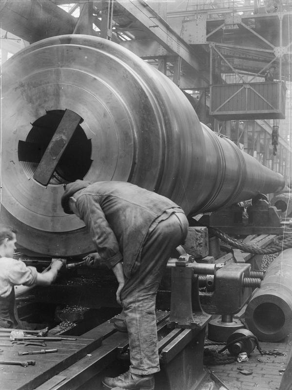
15 December 2013 - Added photograph of gun barrel
10 February 2014 - Added range for 8crh projectile and note about Resolution training problems after being torpedoed
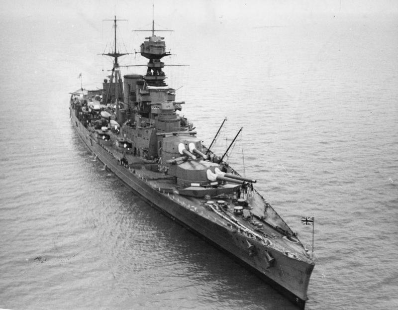
27 February 2014 - Added photograph of HMS Hood
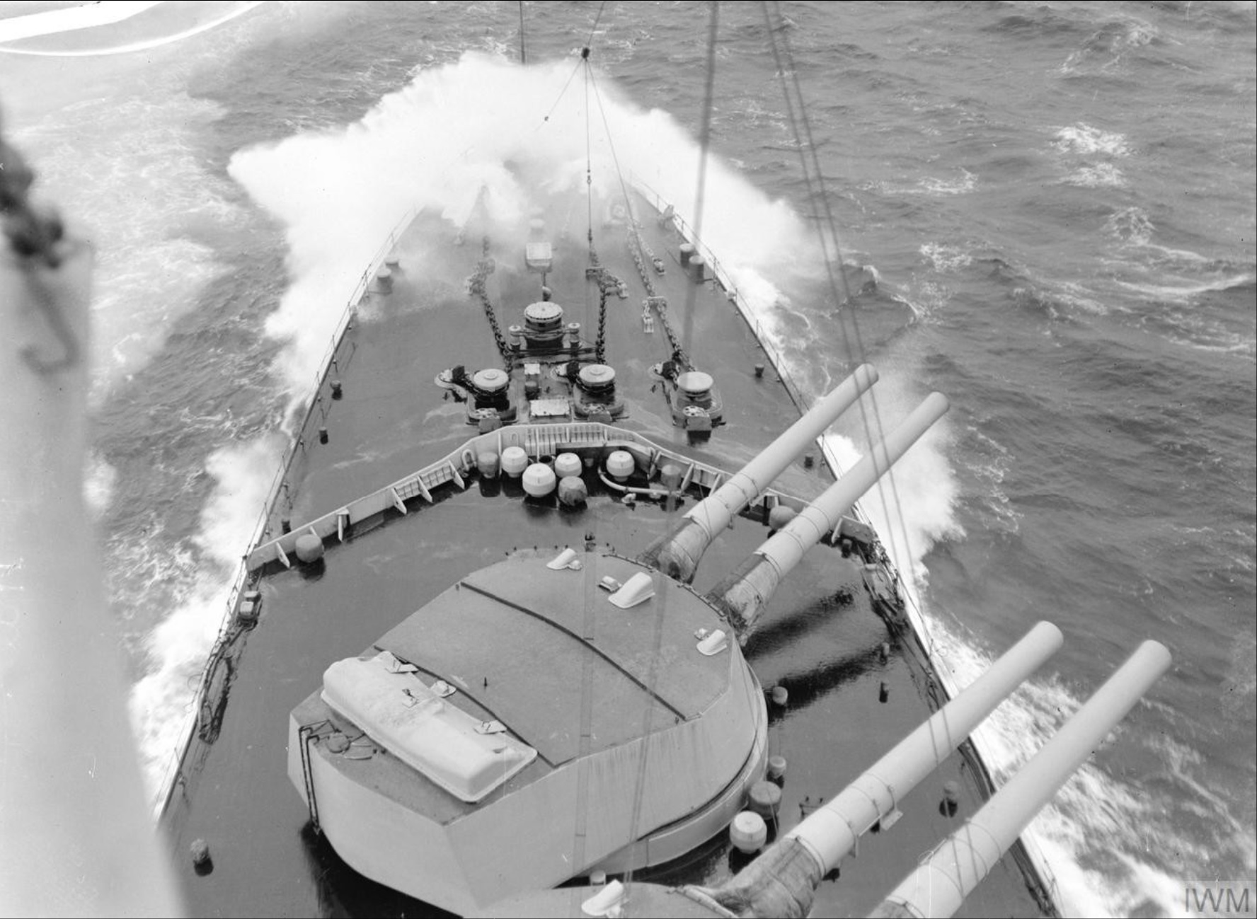
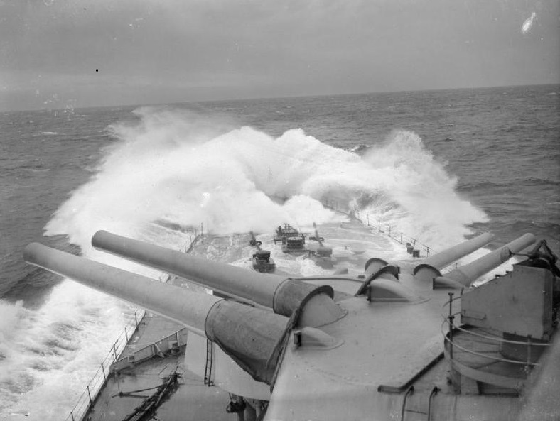
29 June 2014 - Added bow photograph of HMS Vanguard
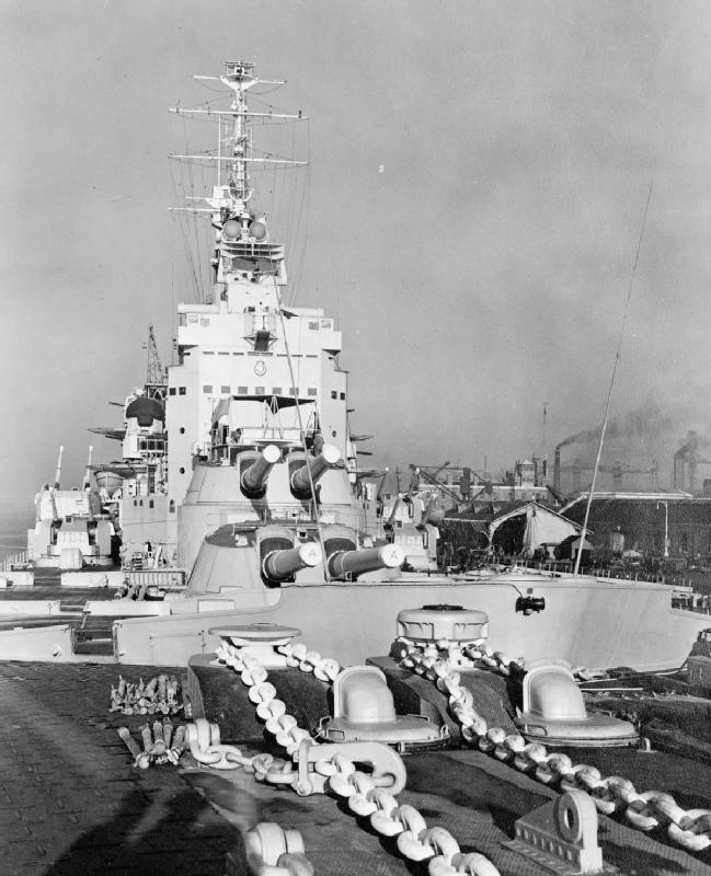
05 October 2014 - Added information to note regarding HMS Vanguard mountings and armor thickness for Glorious class, added bow photograph of HMS Renown
01 December 2015 - Changed Vickers Photographic Archive links to point at Wayback Archive
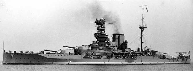
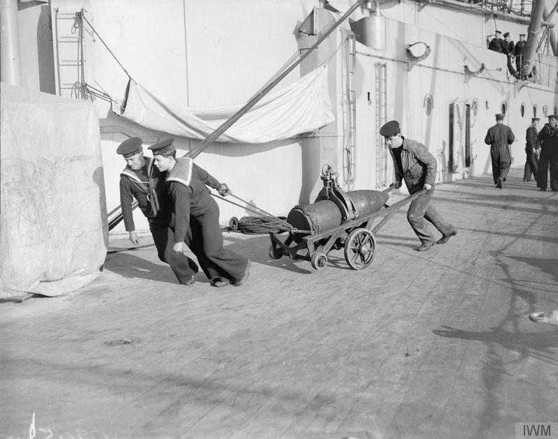
05 March 2016 - Redid photograph of shell handling on HMS Royal Oak
23 June 2016 - Converted to HTML 5 format
28 February 2018 - Reorganized notes
07 August 2018 - Minor changes to improve notes
27 May 2019 - Minor formatting changes, modified notes about Mark I and Mark II mountings, added comments about coastal defense guns at
Singapore and Wanstone, corrected typographical errors, reorganized range section and added notes
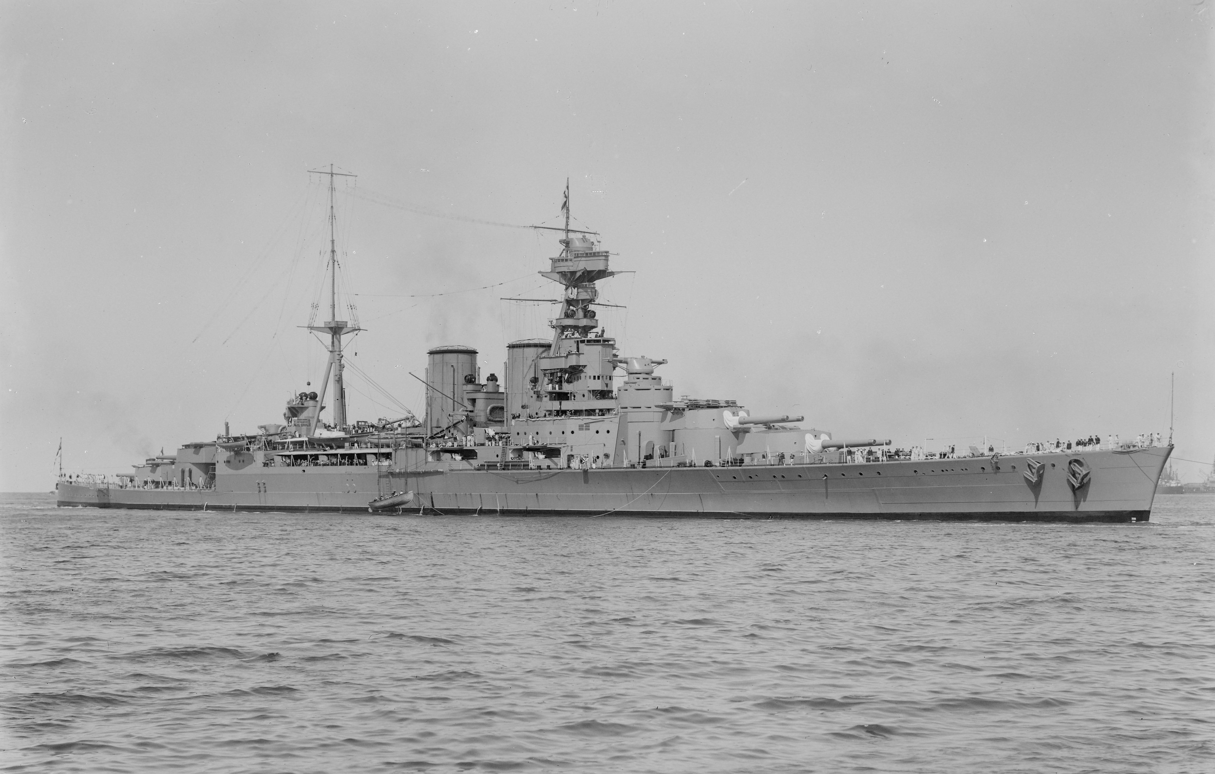
23 July 2020 - Added port side view of HMS Hood
18 October 2020 - Added details about turret armor changes needed for HMS Vanguard, comments about follow-on "Admiral" battlecruisers
14 March 2021 - Added to Mounting / Turret notes
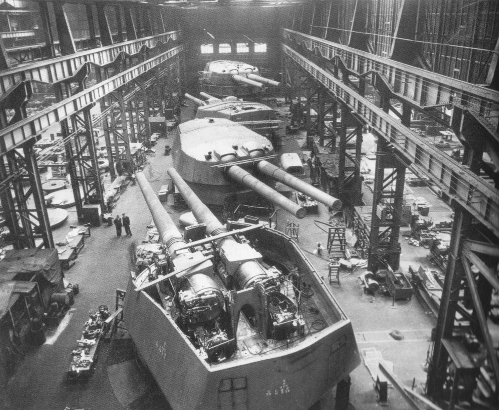
30 April 2021 - Corrected thickness of HMS Vanguard front plate and added photograph of Vanguard turrets in workshop
13 June 2021 - Added note regarding APC Mark Va and Mark VIIa shells used during Baden trials
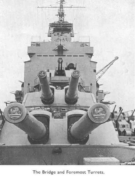
27 December 2021 - Changed link to Cyberheritage to point at Wayback Archive, added photograph of bow turrets on HMS Royal Oak,
minor additions to Ammunition and Mount/Turret Sections
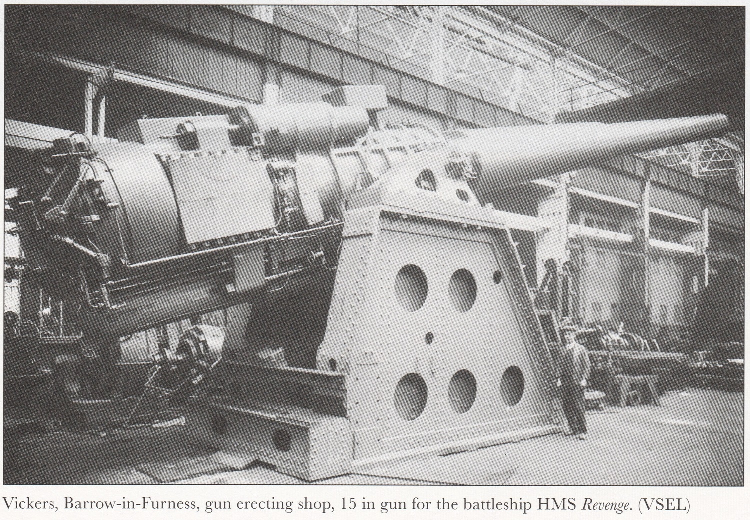
16 August 2022 - Added photograph of 15"/42 Mark I gun in workshop
26 December 2023 - Added sketch of CPC
21 May 2024 - Minor additions to the Ammunition section
22 December 2024 - Minor additions to the Ammunition section
09 March 2025 - Added notes about modernized battleship outfits, post-Jutland (Skagerrak) changes and the number and jobs of crewmen in each mounting
14 April 2025 - Added data to range tables, EFC for Super Charges and note about Range Table Temperature and muzzle velocity changes due to propellant temperature changes
