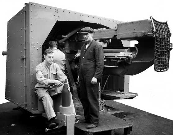
The 4.7" (12 cm) QF Mark IX was used on most destroyers built in the 1930s and 1940s. The almost identical Mark XII was designed for use in twin mountings and differed from the Mark IX in being slightly heavier and longer. Both Marks fired separate ammunition, otherwise they were similar to the preceding 4.7" (12 cm) BL Mark I. A wet-mount version of the Mark IX was developed for submarines, but only a few were in service and these were replaced by standard 4"/40 (10.2 cm) submarine guns prior to World War II.
The lack of a DP function for these weapons was keenly felt throughout the war as more British destroyers were sunk by air attack than from any other cause. What little AA capability that these weapons did have was hindered by a lack of a tachymetric (predictive) fire control system and the setting of HE time fuzes by hand. The last single mounting designed for these guns, the CPXXII, had a spring operated rammer, but all other single mountings were completely hand worked. The twin mounting had power ramming and used power training and elevation but no RPC gear was installed.
Mark IX was constructed of A tube, jacket 80 inches (203 cm) to the muzzle and breech ring. Mark IXA was of loose barrel construction with a removable breech ring. Mark IX* denoted differences in breech ring and semi-automatic breech, which were originally used for two-part wire wound experimental guns. A number of Mark IX* guns were used on destroyers built for Argentina, Brazil and Turkey, but not all of these were delivered. Mark IX** denoted differences in breech ring for CPXVIII mounting. Mark IX**A was for guns converted to loose barrel construction with a removable breech ring. Mark IX**B were new loose barrel guns which differed from Mark IX**A in the breech ring/jacket connection and removable breech ring.
Mark XII was generally similar to Mark IX except that it had a removable breech ring. Mark XIIx had no register on the rear of A tube and breech rings were machined to match. Mark XIIB was of loose barrel construction.
Both the Mark IX and the Mark XII guns could be operated in either Quick Firing (QF) or Semi-Automatic (SA) mode. In QF mode, the breech was manually opened after firing by moving a lever which also ejected the spent casing. In SA mode, the breech would open automatically after firing and eject the spent casing. During loading, the breech mechanism would partially close when the cartridge case rim hit the ejectors and then fully close when the loading tray was raised.
A total of 742 Mark IX and 372 Mark XII guns were manufactured, including all variants. Mark IX**B was one of the largest volume variants, with 183 being made.
Actual bore diameter of all British 4.7" guns was 4.724" (12 cm).
The data that follows is specifically for the Mark IX and Mark XII guns except where noted.
| Designation 1 | 4.7"/45 (12 cm) QF Mark IX
4.7"/45 (12 cm) QF Mark XII |
|---|---|
| Ship Class Used On | Mark IX
Prototype mounted on Mackay
Argentina 2: Buenos Aires class (G class)
Mark XII Prototype mounted on Hereward
Netherlands 3: Van Galen (ii) class (ex-RN "N" destroyers) |
| Date Of Design | about 1928 |
| Date In Service | 1930 |
| Gun Weight | Mark IX: 2.963 - 2.984 tons (3,011 - 3,032 kg)
Mark XII: 3.238 - 3.245 tons (3,290 - 3,297 kg) |
| Gun Length oa | Mark IX: 220.62 in (5.604 m)
Mark XII: 224.08 in (5.692 m) |
| Bore Length | 212.6 in (5.400 m) |
| Rifling Length | 179.3 in (4.552 m) |
| Grooves | (38) 0.037 in deep x 0.270 (0.94 x 6.86 mm) |
| Lands | 0.1205 in (3.061 mm) |
| Twist | Uniform RH 1 in 30 |
| Chamber Volume | Mark IX and Mark XII: 628 in3 (10.29 dm3) |
| Rate Of Fire 4 5 | CPXXII (single) Mounting: 10 - 12 rounds per minute
CPXIX (twin) Mounting: 10 - 12 rounds per minute Other Mountings: 7 - 10 rounds per minute |
- ^Prefixes to the RN gun designations were: C - percussion firing only; D - EMF and percussion; F - EMF (later type breech block); G - DEF and percussion.
- ^Use of Mark IX guns by other nations: Seven modified "G" class destroyers were delivered to Argentina in 1938. At the start of the war in 1939, six "H" class destroyers were under construction for Brazil and four "I" class destroyers were under construction for Turkey. Turkey took possession of two of her destroyers in 1942, but the other eight warships were requisitioned by the Royal Navy.
- ^Use of Mark XII guns by other nations: Two "N" class destroyers (ex-RN Noble (i) and ex-RN Nonpareil) were turned over the the Royal Netherlands Navy in 1942 and became RNN Van Galen (ii) and RNN Tjerk Hiddes, respectively.
- ^As these were all open mountings, bad weather conditions such as experienced by many of these ships on Arctic convoy duty during World War II greatly reduced the ROF figures given above.
- ^CPXXII had spring powered rammers, giving them a higher ROF. All other single mountings were manually rammed. The CPXIX twin mounting had powered ramming which again increased their ROF. See Mount/Turret Data notes below for additional details.
| Type | Separate |
|---|---|
| Projectile Types and Weights 1a | HE: 50 lbs. (22.68 kg)
SAP: 50 lbs. (22.68 kg) |
| Bursting Charge | N/A - TNT |
| Projectile Length | HE: N/A
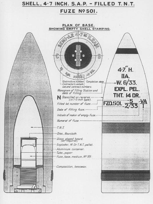
SAP: about 15 in (38 cm) |
| Cartridge Case Type, Size and Empty Weight | Brass, 4.724 x 30.922 in (120 x 785.42 mm), N/A |
| Propellant Charge | 11.58 lbs. (5.25 kg) SC 109
13.13 lbs. (5.96 kg) NF/S 164-048 Cartridge: 30.5 lbs. (13.8 kg) with propellant |
| Muzzle Velocity | 2,650 fps (808 mps) |
| Working Pressure | 20 tons/in2 (2,150 kg/cm2) |
| Approximate Barrel Life | 1,400 rounds |
| Ammunition stowage per gun 2a | Tribals: 200 rounds SAP + 50 rounds HE and 50 rounds star shell per ship
Others: N/A, but probably similar to Tribals |
- ^The projectiles were little if any different from those used for the 4.7" (12 cm)/45 Mark I BL guns as these newer guns were essentially the same weapon converted to use cartridges rather than bag propellants. It is noted by Campbell that "the shells had a mediocre ballistic form." From measuring the sketch shown below, the SAP round appears to be about 3crh.
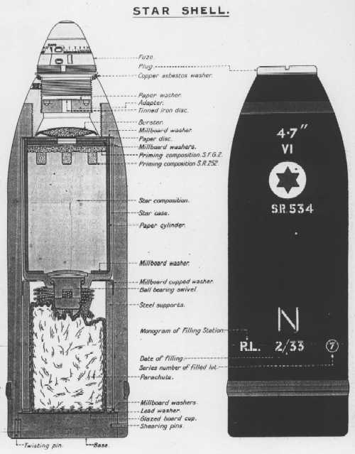
- ^Outfits included SAP, HE and star shells. Ten per gun special anti-submarine HE shells that had RDX/TNT fillers were supplied to each ship by 1945 and star shell complement was 150-200 per ship. VT fuzes were supplied starting in 1944 and by the end of the war these were about 50% of HE projectiles issued.
| Elevation | Distance |
|---|---|
| 30 degrees | 15,800 yards (14,450 m) |
| 40 degrees | 17,000 yards (15,545 m) |
| Designation 1b | Single Mountings for Mark IX Guns
Mackay and Bulldog (4): CPXIII 2b A (4), B (4), C (4), D (4), Codrington (5) and RCN Saguenay (4): CPXIV (a lighter version of this mounting was later used on sloops) Submarine wet-mount (1): CPXVI 3b E(4), F (4), G (4), Exmouth (5), Faulknor (5), Grenville (5) and Hardy (5): CPXVII H (4), I (4), O (4) 4b, Q (4), R (4) and Inglefield (5): CPXVIII S (4) 5b, T (4), U (4), V (4) and W (4): CPXXII 6b Argentina: Buenos Aires (4): N/A (possibly CPXVII)
Twin Mounting for Mark XII Guns 7b 8b |
|---|---|
| Weight | Single Mountings
CPXIII: N/A CPXIV: 8.64 tons (8.79 mt) CPXIV (sloops): 8.13 tons (8.26 mt) CPXVI: N/A CPXVII: 8.83 tons (8.97 mt) CPXVIII: 9.54 tons (9.70 mt) CPXXII 10b: 11.58 tons (11.77 mt) Twin Mounting
|
| Elevation | Single Mountings
CPXIII: -10 (?) / +60 degrees CPXIV: -10 / +30 degrees CPXVI: -10 / +30 degrees CPXVII 11b: -10 / +40 degrees CPXVIII 12b: -10 / +40 degrees CPXXII 10b: -10 / +55 degrees Twin Mounting
|
| Elevation Rate | Single mountings: Manually operated, only
Twin mountings: 10 degrees per second |
| Train | Single Mountings
All but the below: about +150 / -150 degrees "X" position on S, T, U, V and W classes: 360 degrees 13b Twin Mounting
|
| Train Rate | Single mountings: Manually operated, only
Twin mountings: 10 degrees per second |
| Gun recoil | All except CPXXII: 26.5 in (67.3 cm)
CPXXII: 18 in (45.7 cm) |
- ^The mounting types used on the LCG (L) 3 class, on depot ship Barracuda and on DEMS Rochester Castle are unknown.
- ^These guns were first trialed on HMS Mackay in a clumsy CPXIII mounting which allowed +60 degrees elevation. This particular mounting was removed and then fitted to HMS Bulldog. This mounting was not adopted for British service, but it appears to have been used on ships built for Argentina and Chile. This mounting had a 68 inch (173 cm) trunnion height making it difficult to load at low angles. 55 inches (140 cm) is considered the maximum desirable trunnion height for a 50 - 55 lbs. (22.7 - 24.9 kg) projectile. In this and all subsequent single mountings, ammunition was supplied by hand from the magazines and shell rooms or from ready-ammunition lockers located close to the mountings.
- ^Submarine CPXVI mounts were all replaced during the 1930s with standard 4"/40 (10.2 cm) submarine guns. Four CPXVI were converted for use on destroyers and one of these was carried by HMS Acasta.
- ^In order to improve their AA capabilities, four of the "O" class destroyers received old 4" (10.2 cm) guns in lieu of 4.7" (12 cm) guns.
- ^The "S" class destroyer HMS Savage did not receive these 4.7" (12 cm) guns as did her sisters, as she was instead used as a test bed for the 4.5" (11.4 cm) guns that later used on the "Battle" class destroyers.
- ^The CPXXII single mounting had a spring-operated rammer, a single-shell fuze setting machine and a shorter recoil stroke. This mounting also enjoyed a higher elevation (+55 degrees) than in previous mountings, but it was still inadequate for AA purposes. The spring-operated rammer feature was interesting. The rammer spring was cocked by the recoil of the weapon. When the loading tray was pushed across into line with the chamber, the spring tripped automatically and operated the ramming head. This moved the shell and cartridge into the breech while at the same time cocking a smaller "rammer return spring." When the loading tray was moved outwards, ready for reloading, the return spring moved the rammer head to the rear. The automatic tray operation was a large improvement over the earlier hand worked versions, but it needed careful adjustment to ensure that the rammer head tripped at the proper time. These mountings may be easily distinguished from earlier ones by the "raked-back" nature of their front shields, a modification necessitated by their higher maximum elevations. The "X" position for ships with this mounting had modified stops which allowed a total training arc of about 580 degrees. This is why many photographs of these ships show this mounting stowed pointing dead ahead.
- ^The CPXIX twin mounting was the first British power mounting specifically designed for destroyers. These guns had a trunnion height 13" (33 cm) higher than the single mountings. This required raising the wheelhouse to enable to helmsman to see over the gun shields. It also made loading the weapons at low elevations more difficult. The gun axes were 38 in (96.5 cm) apart. Guns shared a cradle and could not elevate independently. Each mounting had two dredger projectile hoists which ran vertically from the shell rooms to the deck below the guns except for "Y" mounting on the Tribal class where the hoists terminated on the upper deck. The projectiles for "A", "B" and "X" mountings were transferred from the tops of the hoists to the gun deck via hand-operated sliding chutes which ran diagonally between the two decks. Propellant cartridges were passed up from the magazines to the guns by hand.
- ^The Tribal class had their four CPXIX mountings split in two groups, each powered by a 140 HP steam turbine and oil hydraulic pump. The J, K and N classes had a 70 HP electric motor and pump on each individual mounting. Elevation was by a hydraulic motor driving pinions on a common shaft which in turn drove arcs fixed to the gun cradles while training was by a hydraulic motor with a similar worm gear. Run out was via compressed air.
- ^Two RCN Tribal class destroyers were completed after the end of the war with four twin 4"/45 (10.2 cm) HA/LA mountings.
- ^The CPXVII mount achieved +40 degree elevation by having a 14" (35.6 cm) gun well with a removable cover which allowed the breech end to go below the deck level. With the cover in place, the mounting could only elevate to 29.5 degrees. "An obviously makeshift design, one wonders how it managed to make it into a service weapon let alone off the drafting table." - John Campbell in "Naval Weapons of World War Two."
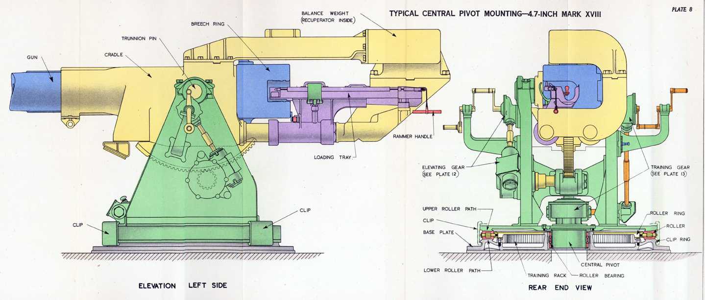
- ^The CPXVIII mounting had the balance weight repositioned above the loading tray which allowed +40 degree elevation without the necessity of the gun wells. These mountings used a circular base plate that was directly bolted to the weather deck and were supported underneath by a ring-shaped bulkhead called the "gun support." A lower roller path was machined on the base ring with a similar upper roller path machined into the underside of the mounting turntable platform. A ring of horizontal roller bearings in these paths held the weight of the mounting. At the center of rotation a light cage held vertical thrust roller bearings and the electrical cabling for fire control and lighting ran up through this cage.
- ^Special stop gear was designed for "X" mounting on the S, T, U, V and W classes to allow a full 360 degrees of train. Whether the mounting was stowed in at zero or 180 degrees was a matter of choice by the ship's captain or by the flotilla commander.
- ^For reasons not known at this time, "X" mounting on the "J" and "K" classes was originally set up such that the mid-training position was dead ahead. This meant that this stern mounting on these ships could not bear directly astern and that having to train from the port quarter to the starboard quarter meant that the mounting had to slew "the long way round" to follow a target passing across the stern. Early in the war, the mountings were modified to move the mid-train position to the more normal dead astern position and the "N" class was completed to this configuration.
- Most of the Tribal class had "X" mounting removed and a twin 4"/45 (10.2 cm) HA/LA mounting installed in its place in order to increase their anti-aircraft capabilities. For similar reasons, the fast minelayers of the Abdiel class had their three 4.7" (12 cm) twin mountings replaced with three twin 4"/45 (10.2 cm) HA/LA mountings. Destroyers of the A-I classes reconfigured as ASW escorts had "A" and "Y" guns removed in order to ship more depth charges and to add a Hedgehog launcher.
- One of the more noticeable features of destroyers with these guns were the large "sprayshields" forward of "B" gun platform and aft of "X" gun platform. Although these structures did reduce spray on the upper decks, their true purpose was to reduce the problem of blast from the upper guns disrupting the crews of the guns on the lower decks. Similar blast shields can be seen on those USN destroyers armed with superfiring open 5" (12.7 cm) pedestal mounts and on German destroyers with superfiring open 15 cm and 12.7 cm mounts. This may be taken as a rather unobvious example of how weapon design influences the design of the rest of the ship. By choosing "lightweight" open mountings for these destroyers, the designers paid a weight penalty in having to add these shield structures. Likewise, the L-M destroyer classes with their "heavyweight" enclosed 4.7" (12 cm) mounts saved some compensating weight by being able to eliminate these shields.
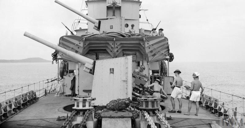


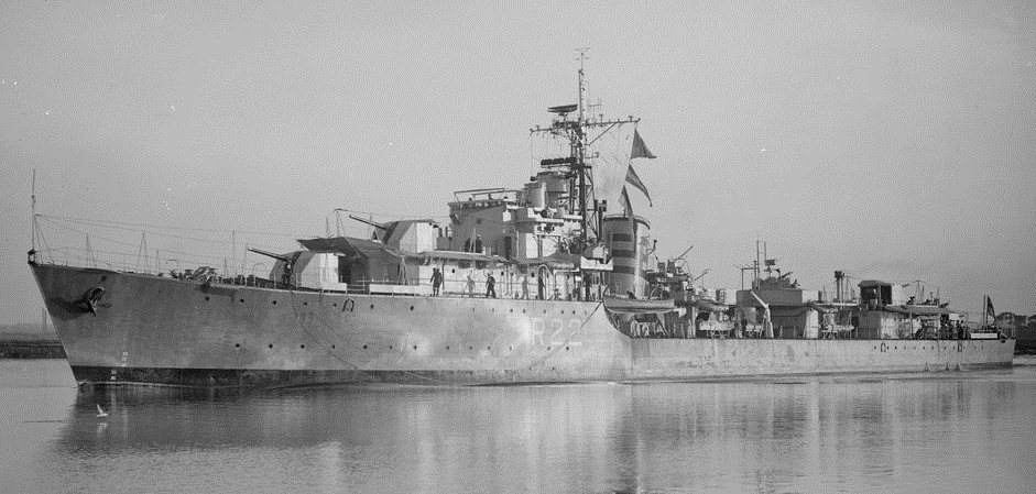

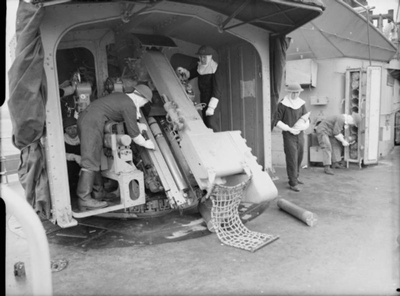
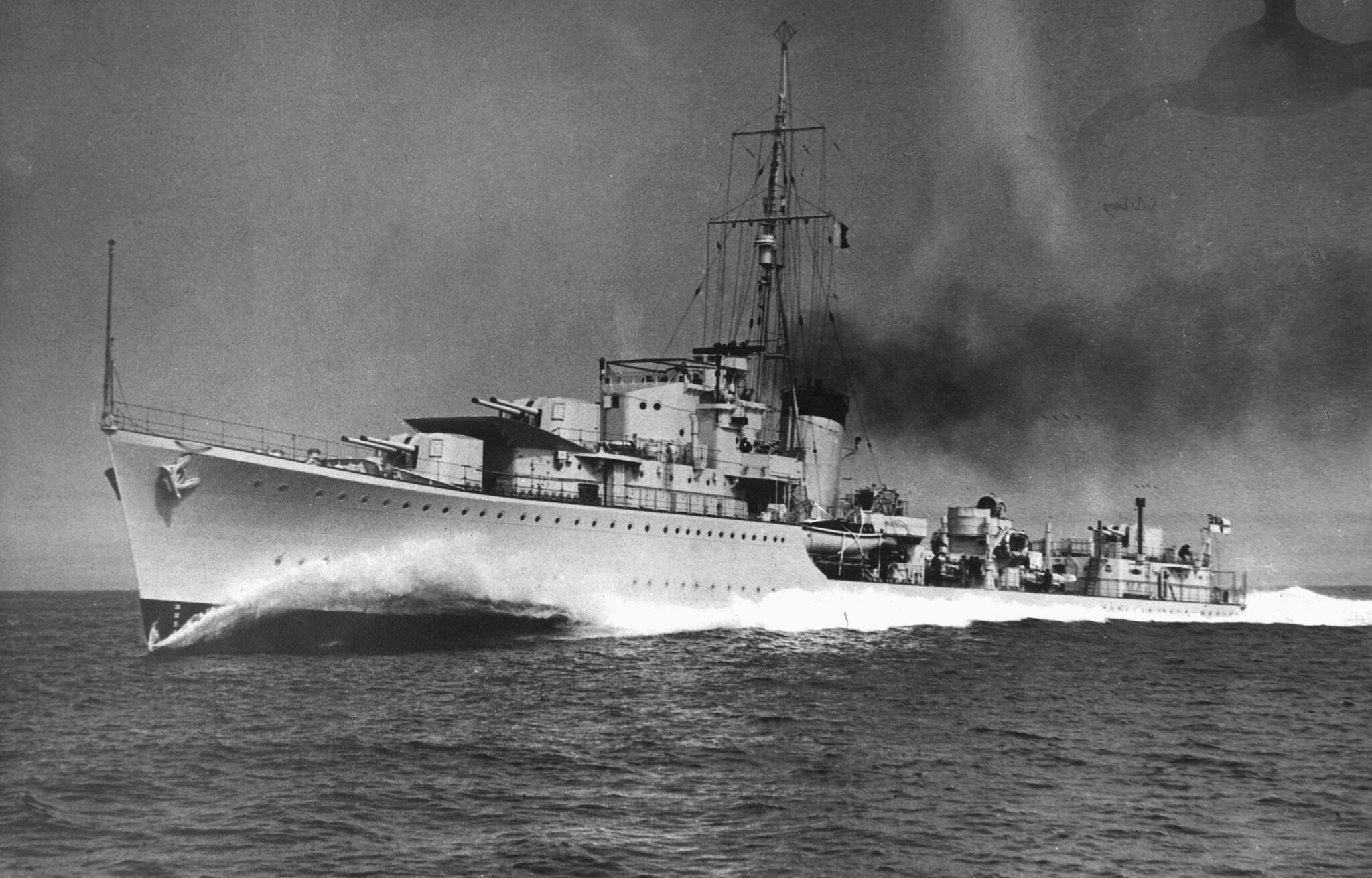
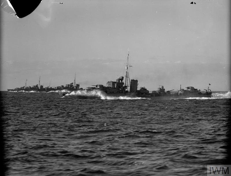
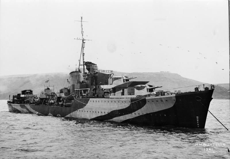
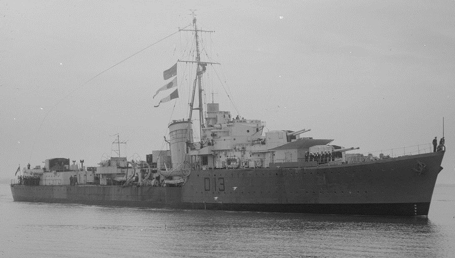
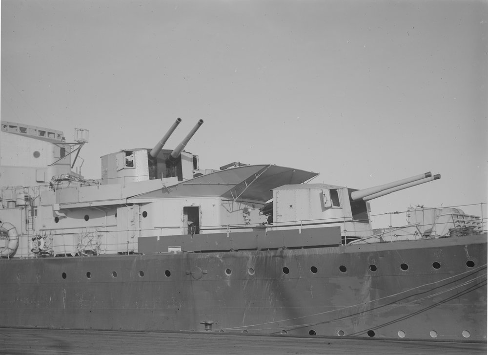
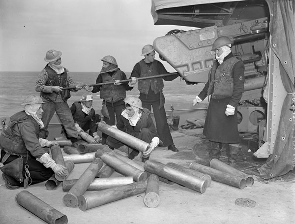
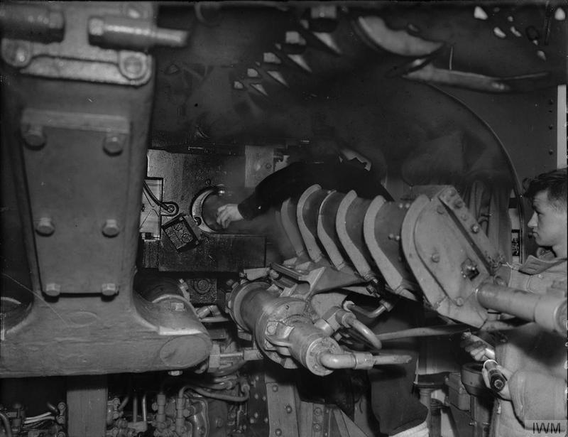
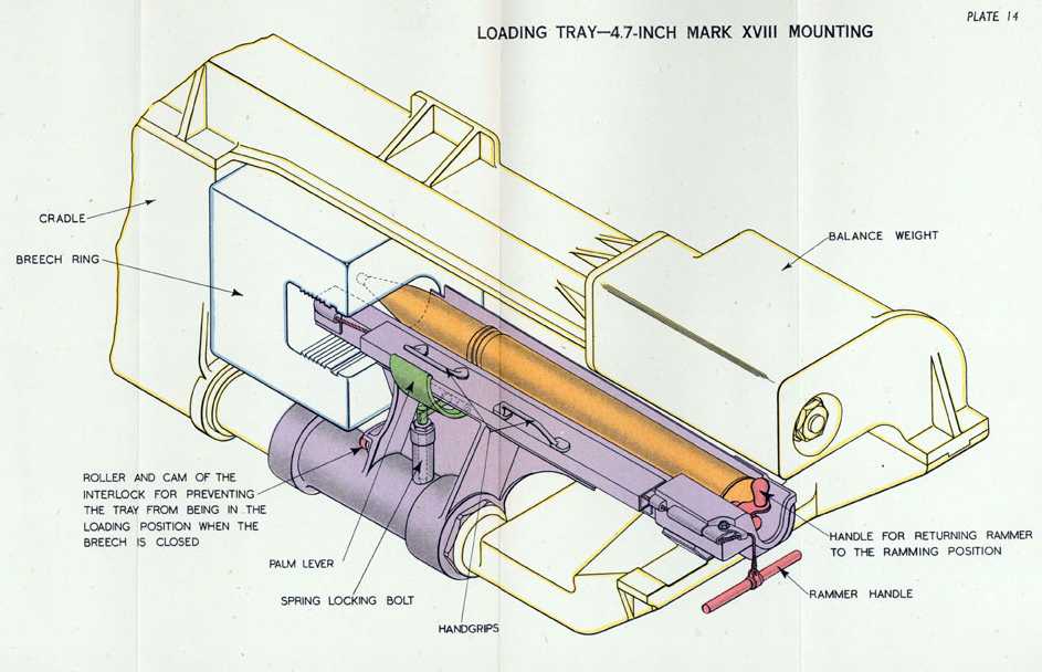

Images at The Vickers Photographic Archive:
- For the Mark IX: 4.7 Mark VIII, Single Mark XIII quarter and XXII. "Mark VIII" is a misprint, the mountings shown here were actually Mark CPXVIII.
- For the Mark XII: 4.7 XIX. Although identified as 4.7" (12 cm) guns, photographs 4797 and 5853 at the Vickers Archives are actually of 4.5" (11.4 cm) twin mounts.
- For the "wet-mount" 4.7" (12 cm) Mark IX guns used on submarines: Thames deck gun.
Images at Australian War Memorial: 112243, 112244, 301076, P00444.206.
"Naval Weapons of World War Two" and "British Naval Guns 1880-1945 No 15" article in "Warship Volume IX" both by John Campbell
"Destroyer Weapons of World War 2" by Peter Hodges and Norman Friedman
"Royal Netherlands Navy" by H.T. Lenton
"British Super Destroyers" article by David Lyon in "Warship Special 2: Super Destroyers" edited by Antony Preston
"Okrety Rzeczpospolitej Polskiej 1920-1946" ("Warships of Republic of Poland 1920-1946") by Stanislaw M. Piaskowski
"British Battleships of World War Two" by Alan Raven and John Roberts
"British Warships of the Second World War" by John Roberts
"Destroyers of World War Two" by M.J. Whitley
---
"An Illustrated Treatise on Ammunition and Ordnance: British 1880-1960" at Steve Johnson's Cyberheritage
---
Tony DiGiulian's personal data files
---
Special help from Andrzej Sluzek
15 January 2008 - Benchmark
30 January 2009 - Added construction details
01 January 2010 - Better identified Brazilian and Turkish destroyer classes
20 August 2010 - Added information on Argentine Buenos Aires class
28 February 2012 - Added SAP projectile length and comment regarding crh
14 November 2013 - Added note about use in Netherlands Navy
22 October 2014 - Minor additions
24 December 2015 - Changed Vickers Photographic Archive links to point at Wayback Archive
09 March 2016 - Moved Vickers "E" gun to its own datapage
03 August 2016 - Converted to HTML 5 format
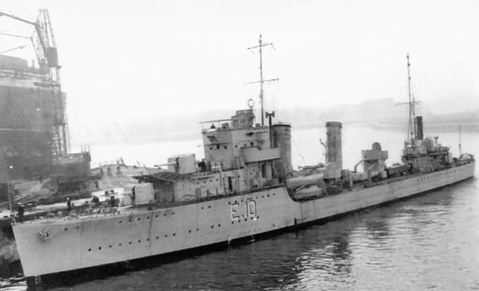
08 August 2017 - Reordered Notes and added photograph of HMS Foxhound
06 November 2017 - Added information on ammunition supply.
01 April 2019 - Reorganized notes
31 August 2019 - Added comments about breech mechanism in QF and SA modes
28 June 2020 - Added comments regarding CPXXII mounting, training of "X" mountings and added photographs of HMS Javelin and K class
22 January 2021 - Added photograph of HMS Kelly
06 November 2021 - Corrected typographical error, minor changes to upgrade to latest template
