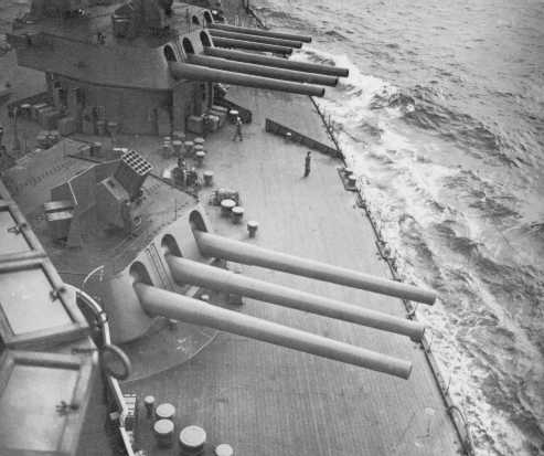
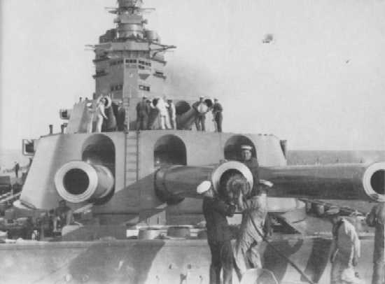
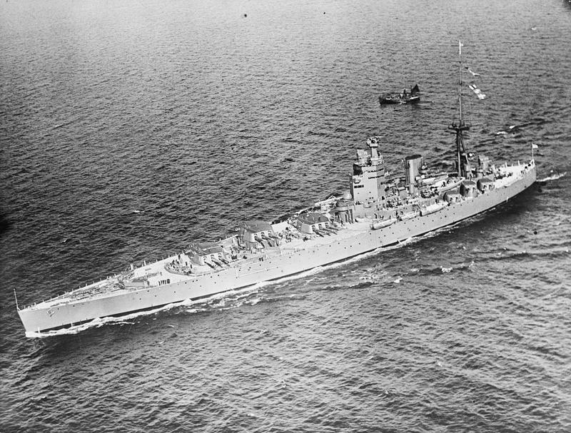
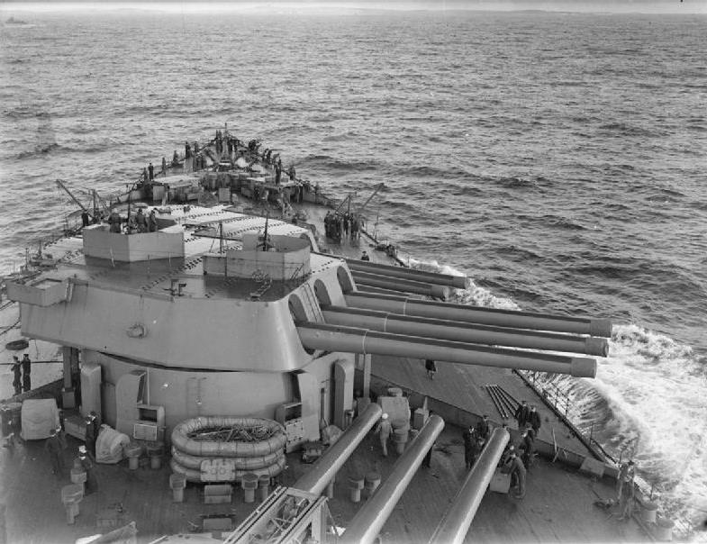
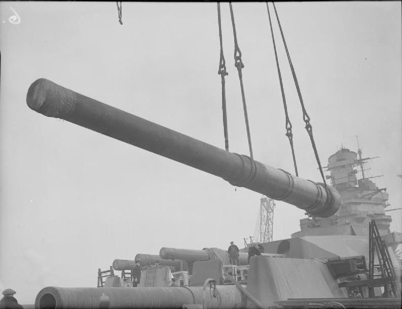
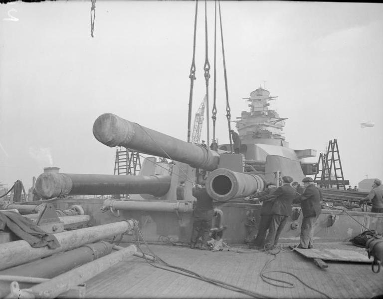
These weapons were originally intended to be used on the never-built "G3" battlecruisers. When those ships were canceled as a result of the Washington Naval Limitation Treaty, the guns and mountings already on order were redesigned slightly and then used on the only two British battleships built during the 1920s, HMS Nelson and HMS Rodney. These were the last wire-wound guns built for the Royal Navy and the only ones to see service mounted in triple turrets. The unusual all-forward turret arrangement was adopted in order to save weight, as this meant a reduced citadel length and thus less armor. A similar approach was taken in the later French Dunkerque and Richelieu designs.
From inadequate firing trials, a mistaken theory was promulgated by the Director of Naval Ordnance (DNO) that held that a high-velocity, low-weight projectile would have superior armor penetration characteristics at large oblique angles of impact, a conclusion which was the opposite of previous findings. This theory was not substantiated by later trials, but these took place too late to affect the decision to use a lightweight APC projectile for new designs. As a result, these guns proved to be only marginally better in terms of armor penetration than the previous 15"/42 (38.1 cm) Mark I and much less satisfactory than those older guns in terms of accuracy and barrel life.
Numerous problems with liner wear, interlocks and turret roller-bearings were found and corrected in the late 1920s and early 1930s, but it was not until 1934 that Nelson's guns were first fired in a long, sixteen rounds per barrel, all-gun sequence. A number of breakdowns occurred during this test, resulting in an energetic effort to correct the deficiencies. By 1939 the majority of the problems found had been rectified. However, these mountings were never trouble-free during the careers of Nelson and Rodney and they cannot be considered to have been a successful design. Nevertheless, it should be noted that these guns on Rodney proved to be more reliable than did the new 14" (35.6 cm) guns on HMS King George V and HMS Prince of Wales during the two battles with the German battleship Bismarck.
Constructed of a tapered inner A tube with two rear locating shoulders, A tube, full length taper wound wire, B tube, overlapping jacket and breech ring, and a shrunk collar on the rear of the A tube. A breech bush was used to attach the Welin breech block which was operated by an Asbury hydraulic mechanism. Some 29 guns were made by Elswick, Vickers, Beardmore and the Royal Gun Factory.
| Designation | 16-inch Mark I |
|---|---|
| Ship Class Used On | Nelson class |
| Date Of Design | 1922 |
| Date In Service | 1927 |
| Gun Weight | With Breech mechanism: 108 tons (109.7 mt)
Without Breech mechanism: 106 tons (107.7 mt) |
| Gun Length oa | 742.2 in (18.852 m) |
| Bore Length | 720.0 in (18.288 m) 45 calibers |
| Rifling Length 1 | Mark I rifling: 586.96 in (14.909 m)
Three guns with short chambers: 592.4 in (15.047 m) Mark II rifling: 588.95 in (14.959 m) |
| Grooves | Mark I rifling: (80) 0.135 in deep x 0.377 (3.43 x 9.577 mm)
Mark II rifling: (96) 0.124 in deep x 0.349 (3.15 x 8.865 mm) |
| Lands | Mark I rifling: 0.2512 in (6.380 mm)
Mark II rifling: 0.1745 in (4.432 mm) |
| Twist | Uniform RH 1 in 30 |
| Chamber Volume 2 | 35,205 in3 (576.9 dm3) |
| Rate Of Fire 3 4 5 | 1.5 rounds per minute |
- ^The different riflings were mixed on each ship and even in each turret. According to "Naval Weapons of World War Two," this was unique as "such differences were totally at variance with the usual British policy for heavy guns in important ships" whereby every effort was made to ensure that each ship had guns of uniform characteristics. As completed, both ships had all Mark I rifling. Nelson in May 1944 received guns with Mark II rifling for "B" and "X" turrets, but "A" turret was not changed until March 1945. For Rodney, in December 1937 "B" turret was changed to two guns with Mark II rifling and one gun with Mark I rifling. In 1938, her "X" turret was fitted with three new guns with Mark I rifling and "A" turret received three new guns with Mark II rifling in February 1942. This mixing on Nelson and Rodney caused initial dispersion problems due to the differing muzzle velocities, but these reportedly became less pronounced as the guns wore.
- ^The sources below disagree as to the chamber volume for these guns. One source says that the volume was originally 35,000 in3 (573.5 dm3), but this was decreased to about 30,000 in3 (491.6 dm3) when muzzle velocity was reduced to increase barrel life (see below). Guns Nos. 3, 4 and 24 had chambers of the same volume as the others but the chamber length was less and the rifled length longer as a consequence. These three guns were used in A turret on Nelson until March 1945.
- ^The following description is adapted from "British Battleships of World War Two:"
The designed loading-cycle for these mounts was 30 seconds, but in practice, it was 35 seconds for one gun. As the shell loading in the handling rooms required 50 seconds, the maximum sustained rate of fire was one round per gun every 50 seconds. However, because of the necessity of firing wing and center guns of turrets in different salvos [in order to reduce dispersion problems], the firing rate was further reduced to one round every 60 to 65 seconds. Even with modifications, the Director of Naval Ordnance considered it extremely doubtful that a greater rate of fire than one round every 40 seconds for the first four rounds and one round every 45 seconds thereafter would actually be achieved.
- ^The average of the full salvo per minute rate for single ship practices between 1928 to 1933 showed a yearly average of 1.90 to 1.53 compared with 2.28 to 1.93 for ships with 15 inch (38.1 cm) guns.
- ^During the "Final Battle" against Bismarck, Rodney fired a total of 380 rounds. For the first hour of the battle, she fired at the equivalent of 1.5 salvos per minute. During the entire battle, she fired 1.6 salvos per minute during salvo firing and 1.1 broadsides per minute during broadside firing with outputs of 77% and 62% respectively (salvos were of four and five guns while broadsides were of all nine guns). The following description of the problems encountered by Rodney is taken from "The Final Action: The Sinking of Bismarck, 27 May 1941" by John Roberts:
She experienced various minor problems with mechanical failures and drill errors, the worst being with the right gun of A turret. This gun missed 11 salvos due to problems with the slide locking gear and then, at salvo 65, a complete jam occurred in the right shell pusher hoist. As a result of drill errors the top shell was rammed up the hoist and jammed in the gunhouse with its nose against the rangefinder supports. It was not cleared until 12 hours after the action. In addition the centre gun of A missed 2 salvos due to slow drill and all the salvos from 64 to 88 due to mechanical failures, the left gun of A missed 10 salvos and did not fire after salvo 97 due to mechanical failures. B turret's centre gun misfired at salvo 4 and missed 5 or 6 over a period of 7 minutes towards the end of the action due to drill errors. The left gun of B had several delays as a result of drill errors but X turret suffered only two jams which caused only minor delays.
| Type | Bag |
|---|---|
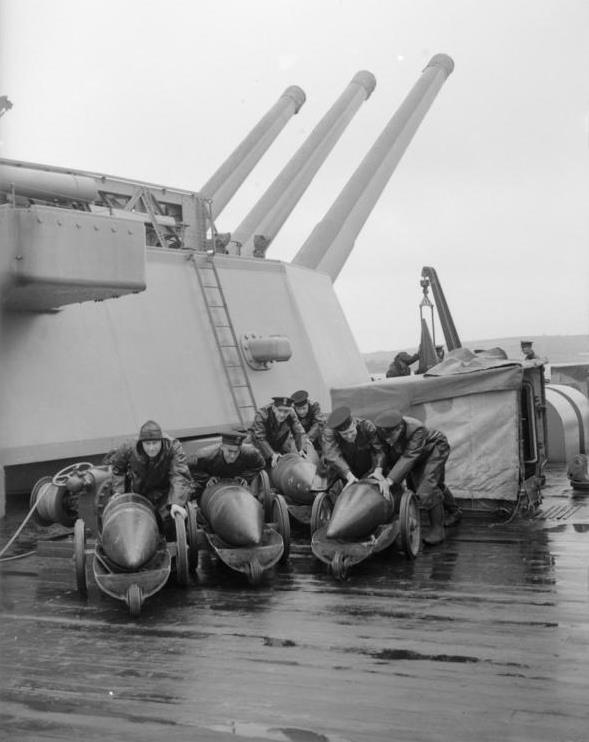
| Projectile Types and Weights | APC Mark IB 1a 2a 3a 4a: 2,048 lbs. (929 kg)
HE Mark IB 1a 5a: 2,048 lbs. (929 kg) HE Mark IIC(?) 6a: 2,048 lbs. (929 kg) |
| Bursting Charge | APC Mark IB: 51.2 lbs. (23.2 kg) TNT
HE Mark IB: 166 lbs. (75.3 kg) HE Mark IIC(?): 155 lbs. (70.3 kg) |
| Projectile Length | APC Mark IB: 66.23 in (168.2 cm)
HE Mark IB: 75.94 in (192.9 cm) HE Mark IIC(?): 68.10 in (173.0 cm) |
| Propellant Charge 7a | Initial: 498 lbs. (225.9 kg) MD45
After 1930: 495 lbs. (224.5 kg) SC280 |
| Muzzle Velocity 8a | New gun Mark I rifling: 2,586 fps (788 mps)
New gun Mark II rifling: 2,614 fps (797 mps) |
| Working Pressure | Mark I rifling: 20.0 tons/in2 (3,150 kg/cm2)
Mark II rifling: 21.3 tons/in2 (3,355 kg/cm2) |
| Approximate Barrel Life | 200 - 250 rounds 8a |
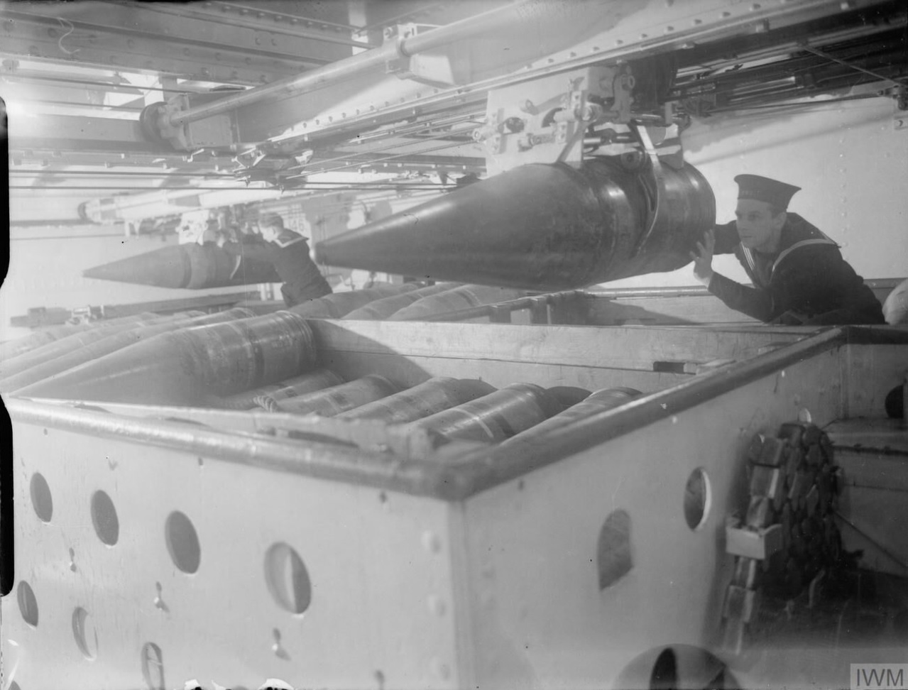
| Ammunition stowage per gun 9a 10a | 95 APC and 10 practice rounds 11a |
- ^The APC Mark IB was unusual for British projectiles in that they used block TNT rather than Shellite as a burster. There was a small (~5% of burster cavity) plaster-of-Paris "shock absorber" in the nose of the burster cavity.
- ^Between late 1942 and early 1943, "K" shell was introduced which contained dyes for coloring the shell splashes. These shells also had a small fuze and burster to disperse the dye. These additions increased the APC weight to 2,059.3 lbs. (934.1 kg). The following colors are listed in a 20 June 1946 Fleet Order:
Rodney: Red
Nelson: None - ^According to "Naval Weapons of World War Two," a heavier 2,250 lbs. (1,021 kg) APC shell was proposed to correct some of the problems encountered by the too-light shell, but "financial stringencies in the early 1930s prevented any change." It was estimated that a 506 lbs. (229.5 kg) charge of SC381 would give this heavier projectile a new-gun muzzle velocity of 2,575 fps (785 mps) and a range of 40,500 yards (37,030 m) at an elevation of 40 degrees.
- ^The original HE projectile had its fuze in the nose of the shell body itself, behind the ballistic cap. This poorly conceived arrangement caused many to fail to detonate. This problem apparently was known at least as early as 1938 and is noted in "Proceedings of the Ordnance Board 1938 MEMO. 1,679." The HE IB shells were withdrawn from service in 1943 after Rodney's bombardment at Oran during the North Africa landings highlighted the problems.
- ^The HE Mark IIC(?) was the replacement for the Mark IB. This later HE projectile was issued about 1944, had a true nose fuze and was of better ballistic shape - 6/12 crh. It was planned to issue this same projectile for the Lion class. Not certain of the actual designation for this projectile, but it was based upon the Ordnance design D.D./L/ 9145. The details listed here are taken from "Proceedings of the Ordnance Board 1938 MEMO. 1,679."
- ^The propellant charge was in six bags.
- ^8.18.2"British Battleships of World War Two" credits these guns as being originally designed with a muzzle velocity of 2,700 fps (823 mps) and a maximum range of 41,983 yards (38,389 m). The very first test firings of these guns found that they had a serious wear problem, with a barrel life of only 180 rounds. It was also found that there was a considerable loss of accuracy during continuous firing, as there was a tendency for the projectiles to strip the rifling out of the guns ". . . due to the hammering action of the short bodied, long headed projectile on its way down the bore . . ." As a result, the rifling in the liners was changed (known as Mark II rifling) for newer guns, the powder charge and chamber size were reduced to the figures shown in the tables above and the diameter of the projectile driving band was increased. Even with these changes, the barrel life and accuracy still compared poorly with the previous 15"/42 (38.1 cm) Mark I.
- ^The original outfit was entirely APC. HE rounds were added later, apparently sometime in the 1930s.
- ^The canceled "G3" battlecruiser design had a planned ammunition stowage per gun of 80 APC, 20 CPC, 6 shrapnel and 10 practice. This was the wartime outfit, the peace or "legend" outfit was 80 rounds per gun. Stowage was provided for a total of 116 projectiles and 100 powder charges per gun.
- ^As commissioned, HMS Nelson had an actual capacity of 381 shells in "A" mounting, 387 shells in "B" mounting and 303 shells in "X" mounting, an average of 119 per gun. For treaty compliance purposes, she was listed as having 80 rounds per gun. All ammunition rooms were adjacent and shells could be transferred through watertight doors to the other mountings.
| Elevation | Range | Striking Velocity | Angle of Fall |
|---|---|---|---|
| 2.3 degrees | 5,000 yards (4,570 m) | 2,248 fps (685 mps) | 2.5 |
| 5.1 degrees | 10,000 yards (9,140 m) | 1,996 fps (608 mps) | 5.9 |
| 8.5 degrees | 15,000 yards (13,720 m) | 1,778 fps (542 mps) | 10.2 |
| 12.5 degrees | 20,000 yards (18,290 m) | 1,606 fps (490 mps) | 16.5 |
| 17.5 degrees | 25,000 yards (22,860 m) | 1,486 fps (453 mps) | 24.6 |
| 23.7 degrees | 30,000 yards (27,430 m) | 1,431 fps (436 mps) | 33.5 |
| 32.4 degrees | 35,000 yards (32,000 m) | 1,453 fps (443 mps) | 43.7 |
| 39.2 degrees | 37,500 yards (34,290 m) | 1,503 fps (458 mps) | 50.5 |
| 40.0 degrees | about 38,000 yards (34,750 m) | --- | --- |
Time of flight for APC Shell with MV = 2,525 fps (770 mps)
10,000 yards (9,140 m): 13.4 seconds
20,000 yards (18,290 m): 31.1 seconds
30,000 yards (27,430 m): 54.7 seconds
37,500 yards (34,290 m): 82.8 seconds
| Elevation | With AP Shell |
|---|---|
| 40 degrees
With Mark I rifling New gun MV of 2,586 fps (788 mps) |
39,090 yards (35,745 m) |
| 40 degrees
With Mark II rifling New gun MV of 2,614 fps (797 mps) |
39,780 yards (36,375 m) |
| Elevation | With late-war HE Shell |
|---|---|
| 40 degrees
With Mark I rifling |
40,890 yards (37,390 m) |
| 40 degrees
With Mark II rifling |
41,690 yards (38,120 m) |
These two tables show the difficulties with dispersion that must have been created by the unusual practice of mixing guns with different riflings within the same turret and ship.
| Range | Side Armor | Deck Armor |
|---|---|---|
| 15,000 yards (13,716 m) | 14.4" (366 mm) | 1.95" (50 mm) |
| 20,000 yards (18,288 m) | 12.2" (310 mm) | 2.85" (72 mm) |
| 25,000 yards (22,860 m) | 10.3" (261 mm) | 3.90" (99 mm) |
| 30,000 yards (27,432 m) | 8.8" (224 mm) | 5.10" (130 mm) |
| 35,000 yards (32,004 m) | 7.6" (193 mm) | 6.50" (165 mm) |
This data is from "Battleships: Allied Battleships in World War II" for a muzzle velocity of 2,525 fps (770 mps) and is based upon the USN Empirical Formula for Armor Penetration.
| Designation | Three-gun Turrets
Nelson (3): Mark I 1b 2b 3b 4b |
|---|---|
| Weight | "A" and "X": 1,464 tons (1,487 mt)
"B": 1,483 tons (1,506 mt) |
| Elevation | -3 / +40 degrees |
| Rate of Elevation | 10 degrees per second |
| Train | "A" Turret: +/- 149 degrees
"B" Turret: +/- 165 degrees "X" Turret: About 60 to 130 degrees on either side |
| Rate of Train | 4 degrees per second 5b |
| Gun Recoil | 44.6 in (113 cm) |
| Loading Angle | +3 degrees 6b |
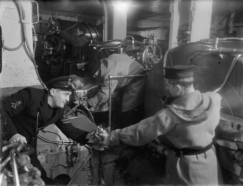
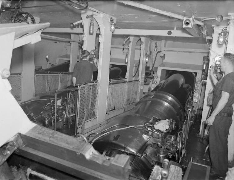
- ^These triple mountings proved to be quite troublesome during their early careers due to their complex design. This complexity was partially due to the nature of mounting three independently sleeved guns, but it was also because of the British excessive use of interlocks in the ammunition loading and supply systems and by the use of a large number of swash-plate engines. There were nearly 50 mechanical interlocks associated with the loading of each gun. Although the anti-flash precautions were good in these mountings, the turrets still lacked flash shields between the guns. Magazines were located below the shell rooms, the first British ships in service to have this arrangement, although both the cancelled "Admiral" battlecruisers and the 1920s cancelled battlecruisers and battleships would also have been completed this way. In addition, there were now handling rooms between the magazines and the powder hoists and between the shell rooms and the shell hoists. Shells and charges now had to be transferred from the fixed structure to bogies in the handling rooms. The handling rooms rotated with the main mounting. Shells were moved horizontally by overhead rails, then turned vertically and loaded onto the bogies. They were then moved to scuttles on the rotating part to one of the three shell pusher hoists.
- ^A number of changes were made to these mountings during construction. Notable among these was the changing of the pressure medium from water to light mineral oil, which allowed the use of steel pipes in the hydraulic system rather than brass pipes as used in earlier designs. This change saved both weight and cost. The change to mineral oil as the hydraulic fluid may also have been to reduce corrosion in the pusher hoists. The shell and powder bag handling was considerably changed during construction as the problems with these systems became more apparent. Independent shell-bogies were replaced by three fixed shell-bogies mounted 90 degrees apart on a shell-bogie ring. This meant that all three guns had to be loaded almost simultaneously with the loading cycle in the shell handling room. The cordite-bogies were replaced by cordite-hoppers in the revolving structure, which greatly increased the manual handling of the bags and thus the number of crew needed in the handling room. Finally, all components of the handling system had to be modified when the diameter of the projectile driving bands were increased as part of the effort to reduce barrel wear.
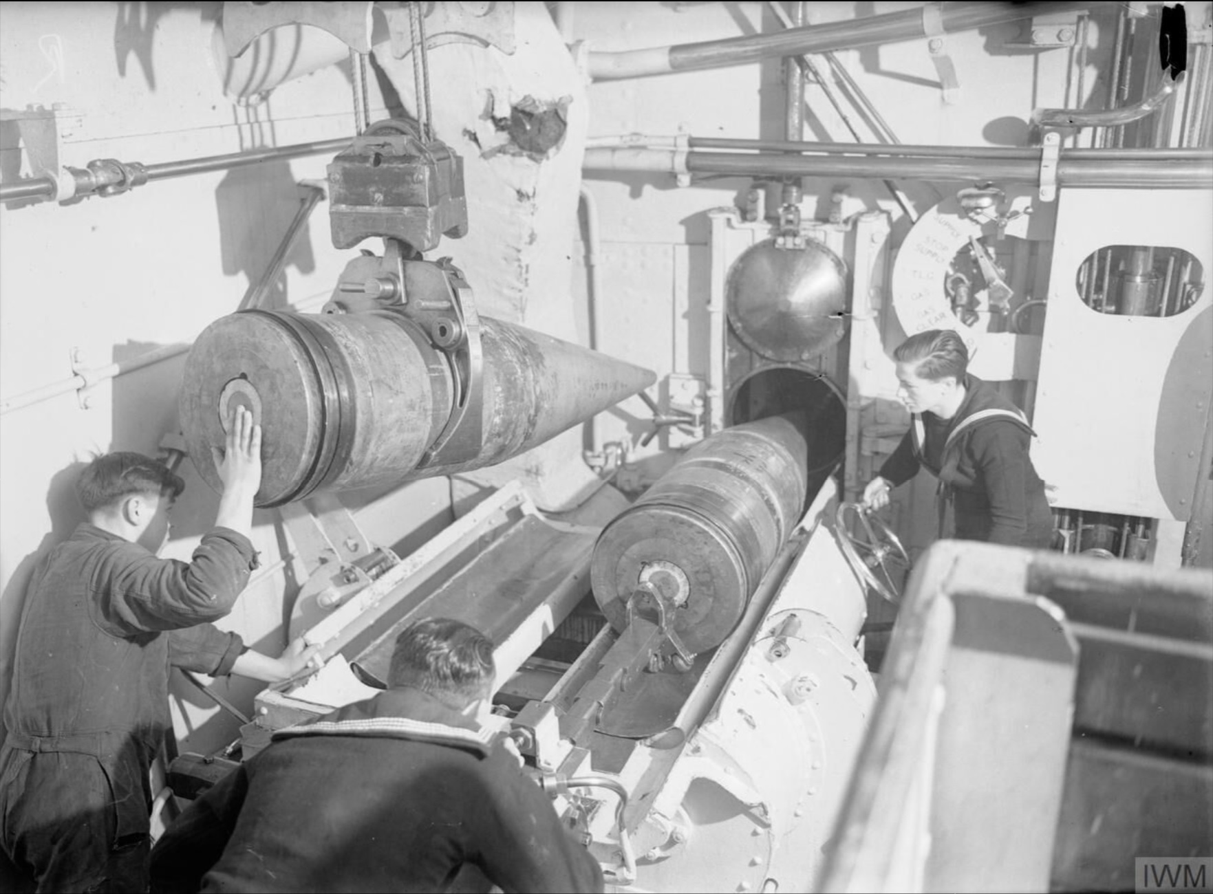
- ^As noted above, these ships did not have handling rooms under the gunhouse. Each gun was served by a pusher shell hoist and a cordite hoist. The shell hoist delivered the shells in a bucket vertically to the rear of the gun. The cordite hoists were a dual canister design, powered by hydraulic rams with wire lift and pulleys, with each canister holding three bags of propellant vertically. These came up to the side and rear of the gun. During loading, the shell bucket tilted horizontally and the rammer went through the bucket to push the shell into the breech. The bucket and cordite canisters then traversed and the first cordite canister was rammed, the arrangement traversed again and then the second cordite canister was rammed. All three then traversed back and tilted vertically before traveling back down for the next load. There were about four ready rounds stored in the wings of the turret. A radial crane moved the ready rounds to the loading trays for the outside guns.
- ^Instead of blast bags, each gun port had a curved mantlet plate attached to the gun cradle.
- ^Rate of Train was limited to 2 degrees per second when the ship's roll exceeded 5 degrees.
- ^The fixed loading angle was a considerable departure from previous designs which strived to achieve "all angle loading."
- The third turret from the bow was designated as "X" turret, not "C" turret. This was apparently done in order to keep a commonality with previous ships. Each turret had its own 750 hp steam engine located in the fixed structure, but any turret could draw on any of the pumps if necessary. Elevation was by hydraulic cylinder and piston connected to the slide. Each turret was driven by two 400 hp swashplate engines, only one in use at a time, which drove a worm gear. Runout was via compressed air.
- An inspection of Rodney's turret roller-paths in 1927 showed that the inner edge of the lower roller path was cutting into the flanges of the turret-rollers. A quickly-ordered inspection of Nelson found much the same problem. The damage was determined to be caused by the lateral thrust created when the heavy turrets were trained, especially when in a seaway. Restrictions were made to the speed in which the turrets could be trained while a solution was sought. After some alterations to the existing design failed to solve the problem, a satisfactory solution was found by the fitting of a new set of vertical rollers to the rotating structure. These were designed to take the lateral thrust away from the horizontal rollers and could maintain the necessary degree of concentricity between the upper and lower roller paths. Some of these vertical rollers were spring-loaded to help even out the forces as the turrets trained. The vertical rollers were also spaced such that no two fixed rollers were exactly opposite one another. Addition of these vertical rollers to both battleships was completed by October 1929 and the restriction in maximum training speeds was eliminated. Similar off-set rollers were later used on the King George V class mountings.
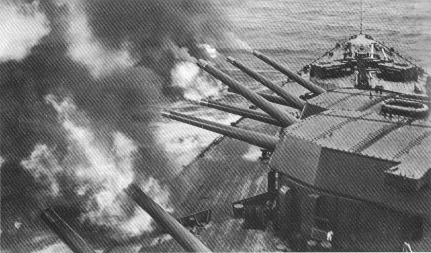
- The all forward design of these ships proved to have disadvantages during their firing trials. Firing "A" and "B" turrets on forward bearings damaged many weather deck fittings and made conditions in the mess deck areas directly below very uncomfortable. The muzzles of "X" turret overhung the deck at nearly all angles of train and elevation. As no astern firing was possible, the superstructure had been cut away to allow large training arcs, but this feature also had its drawbacks. Considerable damage was inflicted to the superstructure and bridge whenever "X" turret was fired abaft the beam, with the bridge becoming almost uninhabitable when the guns were fired at close to 130 degrees and at high elevations. It was suggested that bridge personnel might be moved to the conning tower when "X" turret was firing at angles of 120 degrees or more. Baffles and other additions eased the problems to the bridge area, but they by no means solved them nor dealt with the weather deck problems. Peacetime restrictions on arcs of fire were instituted as a result. The training arcs shown in the table above are the maximum possible arcs, but the actual firing arcs as restricted were probably significantly less. Not everyone felt that the blast effects were too severe. For example, Constructor H.S. Pengelly made the following report after witnessing a firing exercise aboard Rodney on 16 September 1927:
During the firing of "X" and "B" abaft the beam, I remained on the middle line at the after end of the Admiral's platform. The firing from "B" was not uncomfortable, but there was considerable shock when "X" fired at 130 degrees or slightly less, but at 40 degrees of elevation. The shock was aggravated by one not knowing when to expect fire, but apart from this point, it is understood that the blast recorded at the slots on the Admiral's platform were about 9psi and on the Captain's platform about 11psi. It was noted that 10 degrees more bearing aft made all the difference to the effect experienced on the bridge.
The bridge structure was, in itself, entirely satisfactory, and I was informed by the officers occupying the main DCT forward, that this position was extremely satisfactory, and they would have been ready, throughout the whole of the firing, to fire again in 8 to 10 seconds.
The only damage was to the signal platform - 1 x 18in projector at the fore end - glass smashed, and shutter of another broken.
On the Captain's bridge, four windows broken, a few voice pipes loose. On Admiral's bridge, four windows broken. Number of electric lights put out of action. General damage was little, and the extra stiffening inboard after Nelson's gun trials appear to have functioned well.
- The turret crew for "B" turret was 1 officer and 98 men including those in the handling room, shell room, cordite handling room and magazine. The other turrets had 12 less men in the ammunition supply chain.
- The gun axes were 98 in (249 cm) apart.
- Armor thickness for the Nelson class as given in "Naval Weapons of World War Two" by John Campbell and "British Battleships of World War Two" by Raven and Roberts:
Face: 15.68 in (39.8 cm) (640 lbs.)
Fore Sides: 10.78 in (27.4 cm) (440 lbs.)
Rear Sides: 8.82 in (22.4 cm) (360 lbs.)
Rear: 8.82 in (22.4 cm) (360 lbs.)
Roof: 7.105 in (18.0 cm) (320 lbs.) - The following comments are from the report by Capt. Thomas Hugh Binney (RN) to the Admiralty upon finishing his tour of command of HMS Nelson in 1930:
I hold the opinion that the low-angle gun equipment as a whole, and particularly the 16in main armament, is a very marked advance on any previous capital ship, and should result in improved rate of hitting at all ranges.
On account of various improvements (rangefinders, control apparatus, etc.) as well as the increased size of splashes, long-range firing from Nelson should be more effective in the 25/28,000 yds long-range firing than in Queen Elizabeth at 21/25,000 yds.
[snip]
The 16in triple mounting has been subjected to considerable criticism from time to time, and there is little doubt, that in some quarters the view is held that a triple mounting for heavy guns is not a good investment.
The great advantage of the triple mounting system from construction point of view (which is that the armament can be concentrated in a much smaller space, and will require less of armoured protection) has not, perhaps been sufficiently emphasized.
The main disadvantage of Nelson's triple mounting is loss of output on account of the fact that the three guns cannot be fired together owing to ballistic difficulties, whereas they must be loaded together. This, however, is not in itself a reason for condemning the triple mounting in general.
The mounting may be said to have proved itself, when in October 1929, one turret crew with two years experience, loaded and fired 33 rounds without mishap. The main defects appear to be the roller paths and the rollers.
"British Battleships 1919 - 1945: New Revised Edition" by R.A. Burt
"British Naval Gun Mountings: From 1890: 18-inch to 4.5-inch Mark 8" by Ian Buxton
"Naval Weapons of World War Two", "Washington's Cherrytrees: The Evolution of the British 1921-22 Capital Ships"
article in "Warships Volume I" and "British Super-Heavy Guns Part 4" article in "Warships Volume III" all by John Campbell
"Battleship Nelson: The Story of HMS Nelson" by Ronald Careless
"Battleships: Allied Battleships in World War II" by W.H. Garzke, Jr. and R.O. Dulin, Jr.
"The Big Gun: Battleship Main Armament 1860-1945" by Peter Hodges
"British Battleships of World War Two" by Alan Raven and John Roberts
"The Final Action: The Sinking of Bismarck, 27 May 1941" article by John Roberts in "Warship Volume VII"
---
Proceedings of the Ordnance Board 1938 MEMO. 1,679
Proceedings of the Ordnance Board 1939 NO. 915
---
Special help from Phil Golin and Zhu Shipeng
---
Additional information on these weapons may be found in the History and Technology
essays, The British 16"/45 Mark I Gun and Mounting and
The British 14in Quadruple Mark III Turret.
19 July 2007 - Benchmark
07 January 2009 - Corrected typographical error
11 February 2012 - Updated to latest template
03 June 2012 - Added Capt. Binney's comments, Constructor Pengelly's comments, picture of Rodney firing and turret armor note
29 October 2012 - Added note about shell room and magazine locations
15 December 2013 - Added Additional Picture Page
24 August 2014 - Added additional armor details
23 June 2016 - Converted to HTML 5 format
04 April 2019 - Reorganized notes
29 August 2023 - Added photograph of shell room
29 February 2024 - Added comment about plaster-of-Paris in burster cavity
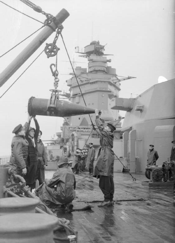
30 March 2004 - Added photograph of ramming a shell into the shell hoist
24 December 2024 - Added HE Burster weights and note about replacement HE Mark IIC(?)
10 March 2025 - Added information to the mounting notes

