Many years ago, I read an article that said that if USS Iowa (BB-61) capsized, she was designed such that her main battery turrets would fall out and the loss of this top weight would then allow the ship to right itself. I was quite impressed with this statement, so much so that a long time later, about 1998, I mentioned it on one of the old NavWeaps forums. Much more knowledgeable people, such as Dick Landgraff and Stuart Slade, "politely" laughed at my naiveté and told me "no, they do not!" Basically, they informed me that not only do the turrets not fall out, but that the water flowing into the ship after it capsized would prevent her from righting herself even if the turrets did fall out.
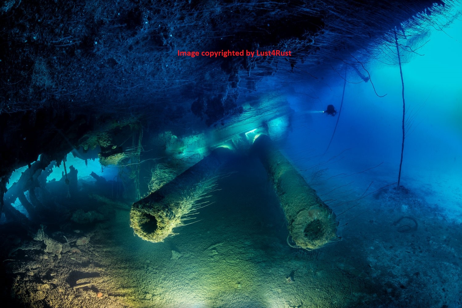
Photograph copyrighted 2015 by Pete Mesley of Lust4Rust and used here by his kind permission.
Since that time, I have seen the "turrets fall out" statement in many different articles about battleships. This is apparently inspired by the discovery of the Bismarck wreck in 1989 by Dr. Ballard where the turrets have indeed fallen out of the ship and lay scattered in the debris field. However, this ignores many other warship wrecks that still retain their turrets within the ship, even though they capsized while sinking. In the case of the Japanese battleship Nagato, as can be seen in the adjacent photograph, her "A" and "Y" turrets have been suspended over the sea bottom for more than 75 years and still have not yet fallen out of the ship.1 Similarly, the floor and stalk of "A" turret on HMS Hood remain in place, although the turret walls, roof and guns were torn away during the sinking.2 3
The reason for these turrets not falling out is because of the presence of "Turret Holding Down Clips" which went into use by most navies around 1900. These clips were metal brackets attached to the rotating structure that hooked around the roller path foundation. They were designed such that if the turret was to start to come out of the roller path, the clips would hit against the bottom of the roller race foundation and stop the turret from upsetting. In the case of Bismarck, the hold down devices may not have been strong enough to prevent them from falling out or they may have been damaged during the battle or possibly they simply were not used by the Germans on this ship (see below). At least some of the earlier ships of the Imperial German Navy did have some means of restraining the turrets. For example, when the German fleet was scuttled at Scapa Flow, some of the capital ships capsized and landed upside down on the sea bed. When these ships were salvaged some years later, the British raised them up still inverted. For the ships armed with 28 cm (11") and 30.5 cm (12") guns, their turrets stayed within their barbettes.4 This led the British to believe that all the ships would be the same, but when it came time to raise the battleship Bayern, a near catastrophe occurred as all four of her 38 cm (15") turrets fell out when they started raising the ship. The wreck, now much lighter than had been calculated, nearly leaped out of the water, only to settle back and sink again.5 Possibly, the design of these 38 cm turrets were copied too closely many years later when Bismarck was constructed.
But before discussing these clips any further, let us review why there are clips in the first place. Turrets, by their nature, are very heavy pieces of equipment that must rotate so as to aim at an enemy warship. For this reason, the turrets are not bolted down and fixed in place but instead rest upon their turret races so that they may turn as needed. On some of the pre-dreadnoughts, the designers may not have mechanically restrained the turrets with holding down clips, but instead relied solely upon their weight to keep them in place. For these warships with their low-powered twin 12" (30.5 cm) turrets, this would have worked fairly well. However, as battleship main-gun batteries became more and more powerful during the late years of the 19th century and early years of the 20th century, the recoil forces also became much more powerful as well. It was feared that the recoil forces had grown so large that the turrets would "jump the tracks" and come out of the roller path, jamming the turret. This problem could also occur when the ship was in a heavy seaway with the ship rolling and pitching, throwing even the heavy turrets out of place. In addition, in the late 1800s and early 1900s, the USN did a fair amount of experimentation to simulate battle damage. In a number of these tests, slugs were fired into turret mounts at point-blank range to see how much damage was done and to find where the vulnerable points were. One of the findings was that a flat-faced slug could exert enough force on a turret to cause it to go out of alignment, particularly if the slug did not penetrate the faceplate, i.e., it expended all of its energy against the faceplate. Along with this, they found that a large explosion in the upper hull could potentially push the weather deck up under the gun tubes and dislodge the turret that way.6 7
The solution for these problems was to utilize holding down clips so as to to prevent turret upsets. In the USN, these were installed at least as early as the "first" American battleship, the Indiana, Battleship #1, completed in 1895.7 As time went on and guns became even more powerful, these clips grew larger and stronger to keep up with both the greater recoil forces and the higher striking forces from enemy projectiles. Eventually the clips grew so robust that they would keep the turret in place even if the ship capsized.
As noted above, holding down clips were in use in the USN as early as 1895. To illustrate how these holding down clips progressed in the United States Navy, let's look at turret design as it progressed from the early dreadnoughts through to the last battleships built by the United States.
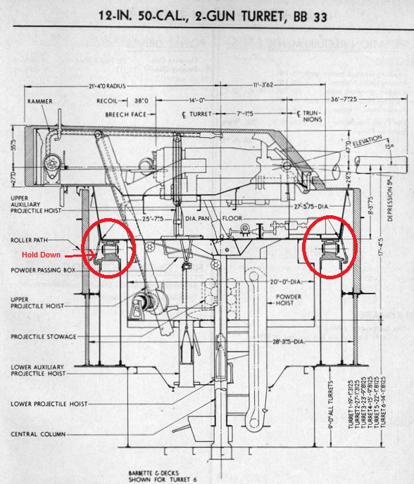
This first sketch8 is for the 12"/50 (30.5 cm) twin turrets as used on the 1912 Wyoming (BB-32) class. As can be seen in this sketch, the holding down clips were simple brackets attached to the turret stalk near the turret race. These hung down and hooked around the turret race foundation, ending just below it. Should the turret try to upset due to recoil or enemy fire, then the clips would hit the bottom of the foundation and prevent the upset.
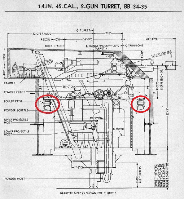
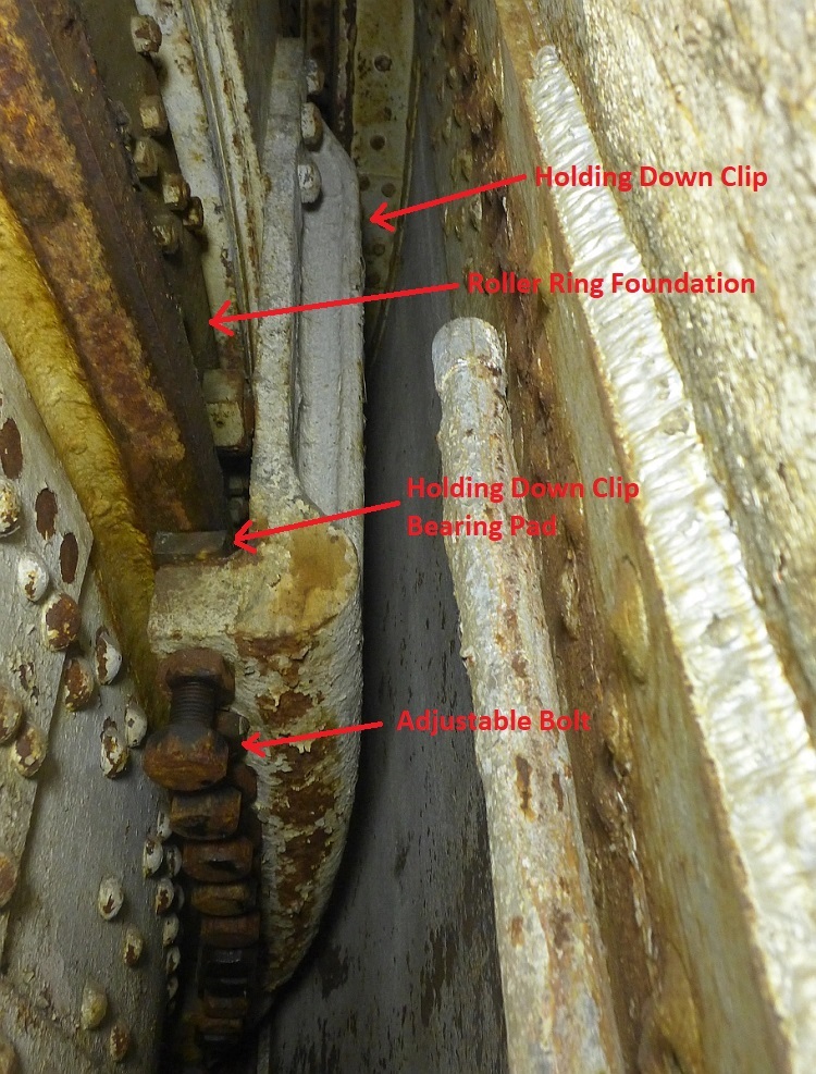
This second sketch8 is for the 14"/45 (35.6 cm) twin turrets as used on the 1914 battleships USS New York (BB-34) and USS Texas (BB-35). The red circles show the roller path. Although none are shown in this diagram, these ships did have holding down clips as may be seen in this YouTube video of the ones on Turret 5 of USS Texas (BB-35). In the adjacent photograph of one of the clips, note that the bottom of the clips have adjustable bolts which control the spacing between a bearing pad and the roller ring foundation. A Bureau of Ships Manual on Turrets says that these bolts should be adjusted such that the gap between the turret race foundation and the holding down clip bearing pads would be no more than 0.125 inches (3.1 mm) and preferably if possible no more than 0.062 inches (1.6 mm).9 If the clips actually touched the foundation, they would create a drag and strain the training gear. The clips were specifically designed so that the bolts could be backed-off locally to allow part of the turret to be "jacked up" so as to permit rollers to be replaced.10
There are a total of five holding down clips for each turret. Three of these are butted together at the front of the turret while the other two are spaced apart at the rear of the turret. This placement shows that the designers were most interested in protecting the turret from upsets caused by recoil and projectile strikes on the front of the turret.11
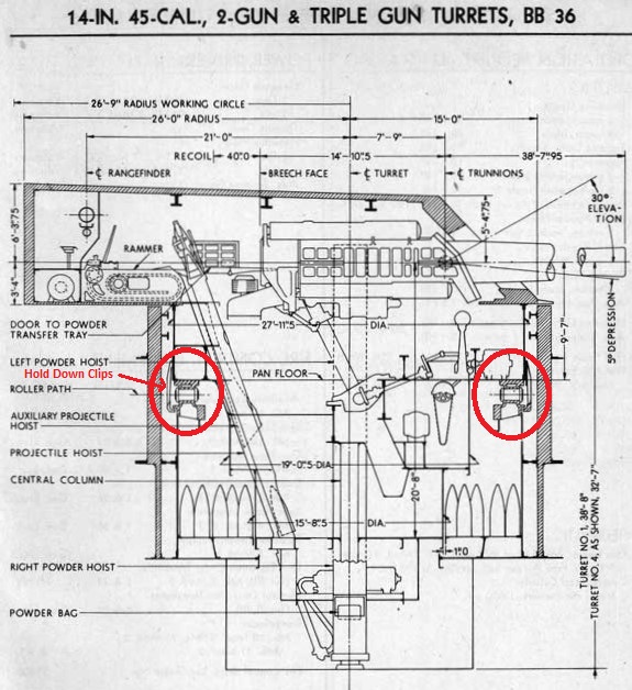

This third sketch8 is for the twin and triple turrets used on the 1916 USS Nevada (BB-36) and USS Oklahoma (BB-37). Like the clips on USS Texas, the turret holding down clips are simple brackets attached to the rotating structure. The triple turrets had seven clips; three forward, one on each beam, and two aft. The twin turrets had six clips, having only one clip on the centerline aft rather than two.10
These clips proved to be quite strong. When USS Oklahoma (BB-37) capsized after being torpedoed at Pearl Harbor, she rotated 151 degrees before her cage masts and superstructure stuck in the bottom mud and halted the roll. She lay like this for over a year before righting operations began on 8 March 1943. The righting operation was a long process, taking over three months to complete. During the initial phase, righting was very slow paced, proceeding no faster than 1.4 degrees per hour for thirteen and a half hours before halting for a day to repair pulling cable connections. Further intervals of slow-paced righting and halting for cable repairs meant that the roll did not decrease to 90 degrees until 11 days had passed. This meant that the inverted turrets were suspended above the harbor bottom during this entire time. Despite battle damage, year-long salt-water immersion and inversion time, her holding down clips had kept her turrets secure in their barbettes as can be seen in the adjacent photograph.12
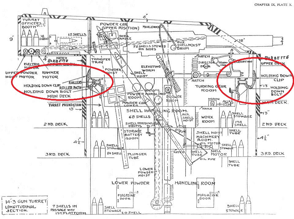
This fourth sketch13 shows a three-gun turret for the 1918 USS New Mexico (BB-40) class, which were battleships equipped with the more powerful 14"/50 (35.6 cm) guns. The simple holding down clips of the earlier ships have now been replaced with this much stronger and more complex design, reflecting the greater recoil force generated by these guns and the equivalent striking force from enemy warships.
In this next set of photographs, we see the much more substantial holding down clips as used on the 1940s USS North Carolina (BB-55), USS South Dakota (BB-57) and USS Iowa (BB-61) classes. The photographs show the Turret II framework being assembled into USS New Jersey (BB-62) and are courtesy of NavSource.
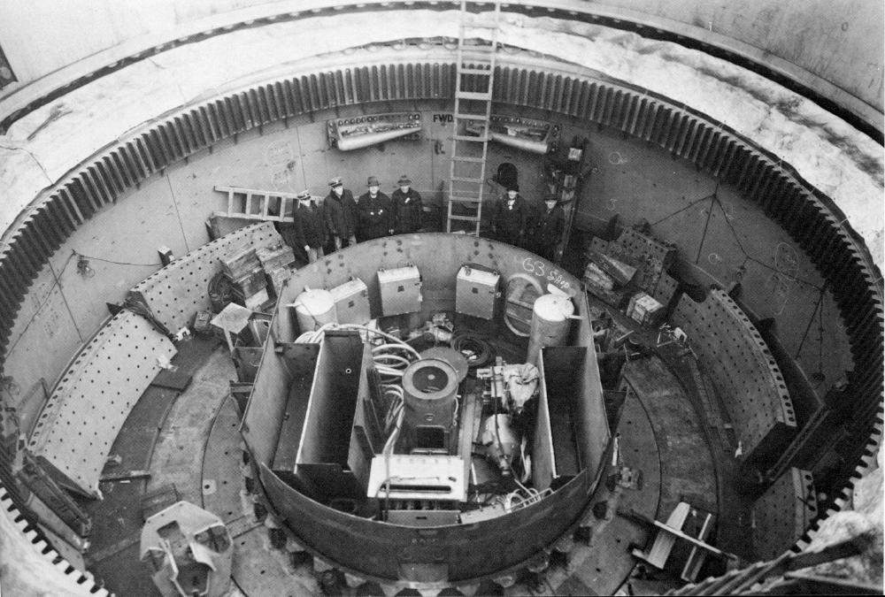
In this photograph, note the holes in the holding down clips. These are used to bolt the clips onto the turret framework.
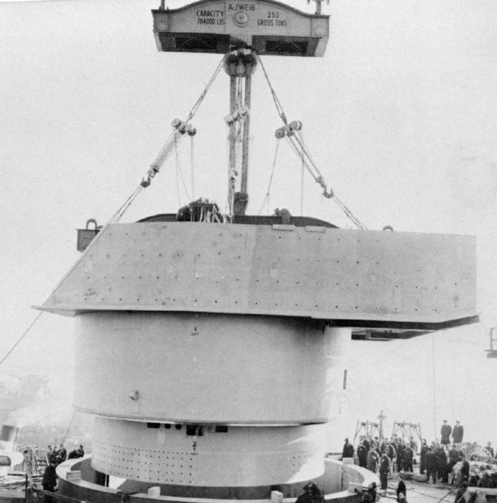
In this photograph, note the bolt holes on the lowest level of the framework. These are used to secure the holding down clips to the turret.
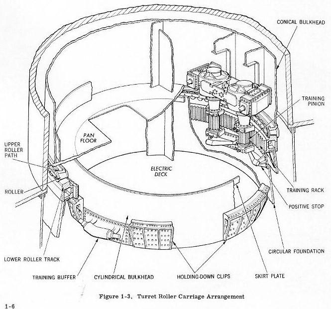
As can be seen in the photographs above, the holding down clips used on the USN "Fast Battleships" were quite substantial and encircled the turret. These would have been able to retain the turrets inside the ship should it capsize, although that was not their intended function.
Although this essay concentrates on battleships, it should be noted that cruiser turrets in the USN also utilized holding down clips to keep them in place. Smaller gun mounts like those for 3" (7.62 cm) and 4" (10.2 cm) guns used a form of holding down clip to keep the gun recoil from knocking over their stands when they fired. Holding down clips were also used on other large, rotating equipment such as gunnery directors.
Notes:
- ^Nagato's superfiring "B" and "X" turrets also did not leave the wreck, but their roofs rest on the sea bed and the wreck rests on top of them. Which is why the other turrets are suspended above the sea floor.
- ^Other examples of ships retaining their turrets:
HMS Royal Oak wreck
HMS Repulse wreck
SMS Derfflinger in drydock after being salvaged - ^S.C. George, "Jutland to Junkyard," pg. 66-98.
- ^S.C. George, "Jutland to Junkyard," pg. 108.
- ^Email from Bill Jurens, 26 February 2022. Off topic, but one of the changes made from these experiments was to provide the turrets with extra large training motors which would allow them to push a fairly substantial amount of junk, such as a cage-mast, that was blocking the path of the guns as they rotated.
- ^7.17.2"A Battleship Turret Tested to Destruction" in Scientific American Volume 74, May 23, 1896, page 331.
- ^8.18.28.3Sketches from BuOrd publication "Gun Mount And Turret Catalog" OP-1112, courtesy of Historic Naval Ships Association (HNSA).
- ^Bureau of Ships Manual: Turrets (1942) Section 72-6. A 1920 version of this document has this same section which is almost word for word with that in the 1942 edition.
- ^Email from Tom Scott, 07 March 2022.
- ^Daniel Madsen, "Resurrection: Salvaging the Battle Fleet at Pearl Harbor," pg. 197-215.
- ^Sketch from "Naval Ordnance 1939," an Annapolis Textbook.
- BB-61 class Turret Roller Carriage Assembly Sketch from "16-Inch Three Gun Turrets BB-61 Class: OP-769" - 30 April 1968 by Bureau of Ordnance (BuOrd), Department of the Navy, pg. 1-6.
- A British version of holding down clips may be seen in this turret sketch in "Anatomy of the Ship: HMS Duke of York" by Ian Buxton and Ian Johnston. See "Turntable Clips" on the right side of the sketch.
Special thanks to Bill Jurens for his help with this essay.
11 March 2022 - New datapage
22 March 2022 - Added information on USS Oklahoma salvage and changed BB-61 class turret sketch

