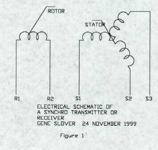
A device called a Selsyn was developed about 1925. This comprised of a system whereby a generator and a motor so connected by wire that angular rotation or position in the generator is reproduced simultaneously in the motor. The generator and receiver are also called, a transmitter and receiver. About 1942 or 43 the term, synchro, became the general term, replacing the word, selsyn. Figure 1 is an electrical schematic of a synchro device.
These devices operate on AC, alternating current, generally 115 volts. The stator has 3 electrical coils, so wound in the stator as to be 120 mechanical degrees apart or in rotation as you prefer. The three coils are center-tap connected as shown. Three leads are brought out into a terminal box on the outside of the device and labeled, S1, S2, and S3. Representing Stator 1, Stator 2, and Stator 3 coils. The stator is mounted so that its position is fixed, manually and its position cannot be easily changed. It stays put. The rotor, is just what rotor implies, it can be rotated, and is usually mounted on ball bearings, although some of the original selsyn devices had sleeve bearings. The rotor has one electrical winding. Its two ends terminate in two slip rings. Carbon brushes ride on the two slip rings, to connect power to the rotor, as it rotates. Two wires are brought out of the device, from the brushes and terminate in the same terminal box as the stator wires. These two wires are labeled R1 and R2. 115 V AC is connected to R1 and R2, for operating power. When the rotor is physically rotated so that its coil lines up mechanically, and electrically, with the S1 coil as shown in Fig. 1. The output voltage between S2 and S3 will be 52 V AC. The output voltage measured between S1 and S2 and also between S1 and S3 will be 78 V AC. This then is said to be the Zero point of the device. As you rotate the rotor, the voltages at the S1, S2, and S3 terminals change according to rotation. As the rotor coil lines up with the S2 or the S3 coil the output voltage moves around but is the same, but on the different terminals, as when aligned with the S1 coil. For this device to be of value to you, you connect another identical device in a manner so that the S1 wires of each device are connected to each other, an also the S2 and the S3 wires of both devices. See Fig. 2.
The R1 and R2 rotor wires of both devices are connected to the same 115 V AC power supply. When the power is turned on, and the rotor of one device is held, the rotor of the second device will mechanically line up with the first device. So you now have two devices that can be located some distance apart, and rotation of one device will cause a like rotation in the second device. It is like having a rubber shaft. The devices are identical, and are what is called "like wired" internally. This means that the electrical windings in each are terminated and labeled so as to be identical in mechanical and electrical location.
The first device, the one you are going to rotate, is called the transmitter. The second device, is called the receiver, even though it is identical to the first device. Now put a dial on the shaft of the transmitter that reads 360 degrees and line it up on a stationary mark at the zero degree reading on the dial. On the receiver, place a similar dial and align it to a stationary mark at the zero degree reading on the dial. Now, as you rotate the transmitter dial to the various degree readings you chose, the receiver will follow and align to those same readings. So the two devices together can measure and transmit accurately, mechanical rotation, electrically without having a mechanical linkage between the two points, and can be some distance apart.
These devices do not have much power. About all that they can do is move a dial or a cam of very little load. However, the cam can move a set of electrical contacts that results in the activation and control of very large motors which can be used to power very big things.
There are two problems that the above device has, as I have described it. But this is a start in understanding the device. As described above, the device is a little sloppy. Also, if you physically hold the receiver and rotate the transmitter 180 degrees and then turn loose of the receiver, they will stay in this position of 180 degrees out. But the receiver will still track the transmitter accurately even though it is 180 degrees out. To correct these two problems is another chapter.
- 3 December 1999
- Updated.


