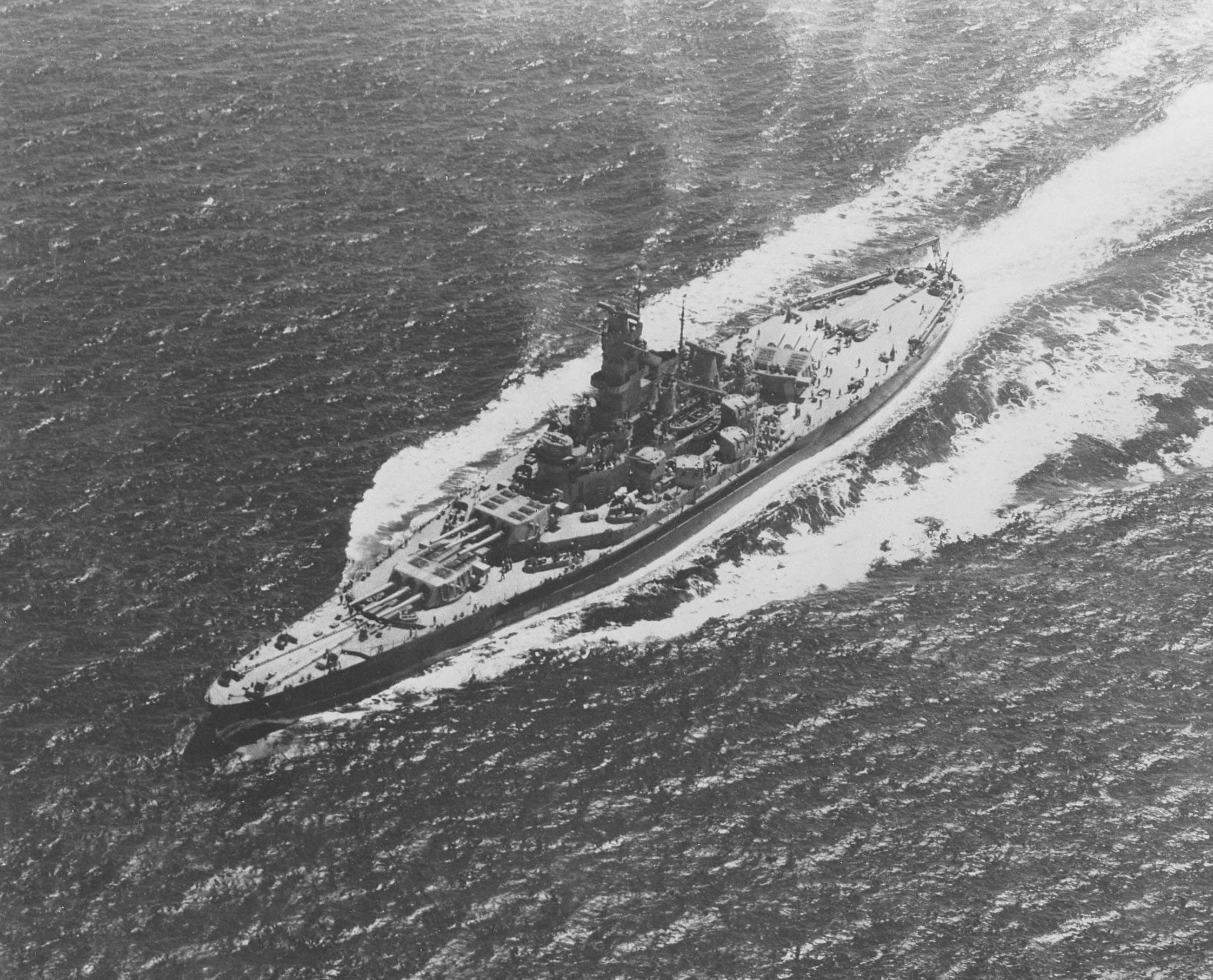
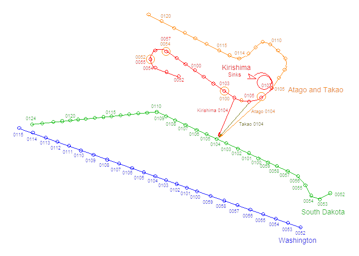
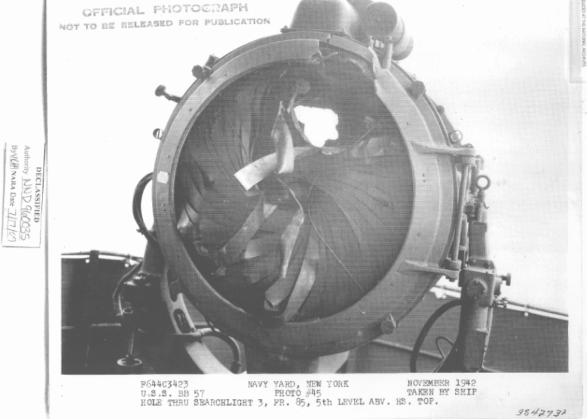
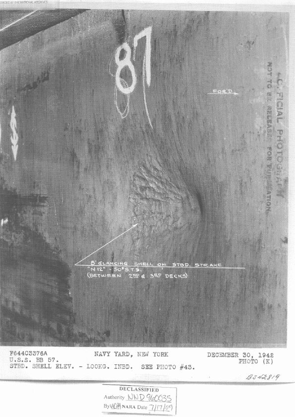
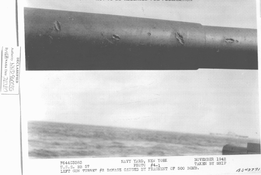
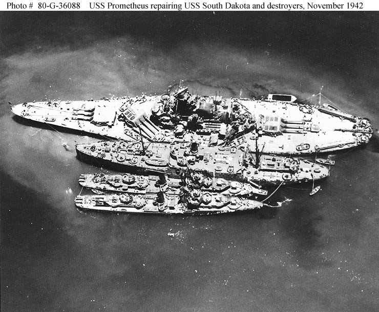
There were only two battleship versus battleship actions fought in the Pacific during World War II. Kirishima's duel with Washington and South Dakota on 14-15 November 1942 was the first of these actions. This battle pitted two of the newest and most modern US battleships against one of Japan's oldest battleships. In this battle, South Dakota was badly damaged while Kirishima was sunk. For a detailed report on this battle, see The Battleship Action 14-15 November 1942. The damage suffered by Kirishima that led to her sinking is discussed in the essay Damage to Kirishima.
As a companion piece to the previous works, the following essay is an attempt to piece together the various historical records of both nations along with a fresh look at the photographic record in order to obtain a fuller picture of the damage suffered by South Dakota during this battle. The authors of this essay have long been aware of the contradictions and errors found in the BuShips report and for that reason have wanted to take a fresh look at the battle damage inflicted to South Dakota in order to provide the reader with a fuller, more accurate accounting of what happened to her that night. Both US and Japanese action reports have been used to reconstruct the battle, determine the types of ammunition fired at South Dakota and when these shots occurred. NAVSEA expert Nathan Okun participated in the writing of this essay and deserves all the credit for determining the Japanese shell types involved in each point of damage. 1
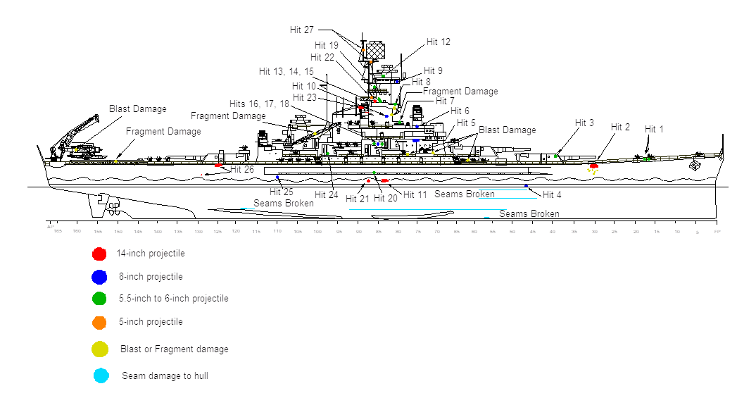
This essay will attempt to illustrate inconsistencies and inaccuracies in the BuShips report, but it will also note where the report seems accurate. In addition, as South Dakota's original action report is confusing in the way that it was written, this essay will attempt to clarify what damage was actually associated with each hit as recorded by the ship's crew and will use both photographs and new sketch drawings to help explain what may have occurred during each hit. In order to assist readers already familiar with this battle, this essay will use the same numbering system of the hits as was used in the original BuShips report. This essay will make a new estimate as to what was the Japanese projectile involved for each individual hit and will detail how the authors made their deductions. If there is not enough information on a particular hit for the authors to make a definitive conclusion, then this essay will note that uncertainty and give the authors' best guesses.
As noted above, many previously unpublished photographs of South Dakota's damage were found while researching for this essay. Any of these photographs that were used to help determine the shell type for a particular hit are included in this essay for reference purposes.
Sketch drawings in this essay were all made by Robert Lundgren and are based upon the BuShips original Builder Plans for South Dakota.
For each hit in this essay, excerpts from BuShips' damage report and from South Dakota's action report are shown indented to indicate direct quotes. In these excerpts, naval phraseology, grammar and abbreviations are left as-is in order to give the reader both the flavor and substance of the documents. Obscure abbreviations are defined in footnotes at their first occurrence. The use of brackets [ ] in these excerpts are used to denote where paraphrasing was used to clarify the meaning of certain passages; where the original photocopy is illegible; or to note the sub-section of the report where the excerpt was found.
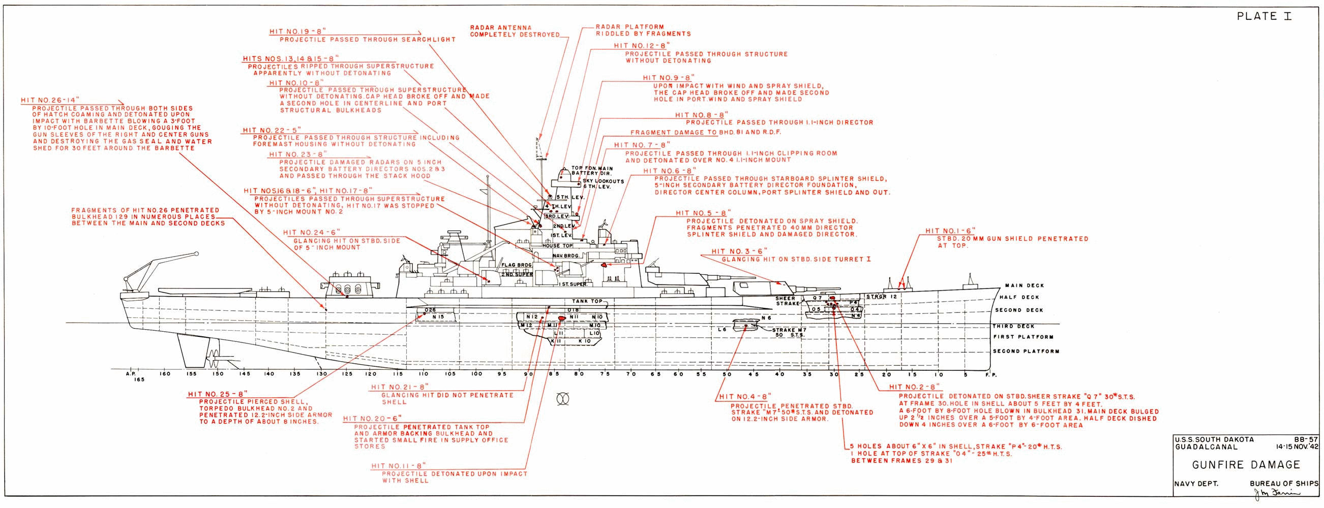
In June of 1947, BuShips issued its report on South Dakota's battle damage. This report counted 26 hits and gave the author's conclusions as to the types of shells that had inflicted the damage found during their examination. This report concluded that South Dakota had been hit by a single 14-inch shell, eighteen 8-inch shells, six 6-inch shells and one 5-inch shell. 2 The accuracy of this report has never been challenged and is now considered as almost a permanent part of South Dakota's history. However, this report should be looked at in light of what was going on in the Navy at the time it was written. South Dakota had already been decommissioned in January 1947 and by the time the report was published the Navy was in the middle of an unprecedented downsizing which saw all but one battleship removed from the fleet to be scrapped or put into mothballs. Carrier-borne aircraft had become the main striking arm of the Navy and battleship construction was now a thing of the past. Surface battles like the one that South Dakota had engaged in were no longer seen as likely to occur in future wars.
For these reasons, the preparation of the damage report had been given a very low priority and the late date of its publication and the paltry seven sources listed as being used in writing it are a reflection of just how low a priority it had. There was no real attempt in this report to reconstruct the battle, no Japanese action reports were used to determine the types of guns and shells fired at her and there was little effort to develop a time line for the action in order to determine just when these hits had occurred. There are many additional photographs of South Dakota's damage in the USN achieves that are not part of this damage report and it is unknown if the authors of the report used any of these in generating it or if they were even aware that these photographs existed. The authors did not even make use of any of the action reports from the other US ships that had taken part in the battle.
In regards to the Japanese memories of the battle, the authors of the BuShips damage report referenced a single United States Strategic Bombing Survey (USSBS) interrogation of a Japanese Naval Officer who was a participant in this battle. This was that of Lieutenant-Commander (LCDR) Tokuno Horishi who was second in command of Kirishima's secondary batteries and who was stationed in the top control point during the battle. This interrogation was superficial at best and is probably most remembered for LCDR Tokuno's estimate regarding the number of hits that Washington had scored on Kirishima. In regards to South Dakota's damage, LCDR Tokuno only said that he thought Kirishima had hit her many times and nothing more. 3
Although even this small comment was largely ignored by the USN, similar observations can be found in the action reports written by other Japanese participants at this battle including that of Admiral Kondo himself. A review of these action reports could have given the original authors of the BuShips damage report many clues in determining the shell types that had struck South Dakota and they may also have learned that Kirishima had opened fire long before the heavy cruisers. This could have been used in determining a time line and the sequence of when hits were made. BuShips had access to these reports if they had wished to use them, as the action reports had been captured and brought back to the United States shortly after the end of the war. In regards to other Japanese documents on the battle, except for one reference document on Japanese eight-inch shells, it appears that none were used in BuShips' damage assessment in order to determine shell types and performance. They did not even use the US Technical Mission's report on Japanese projectile types and fuzes which would have been very useful in determining the kinds of shells that had hit South Dakota. Despite these many omissions, the BuShips damage report has long been taken at face value by most authors of works on this subject.
Footnotes in this essay relating to this damage report are indicated as "BuShips War Damage Report # 57" along with the page number where the data was found.
This document is the official report issued by the ship for this engagement. Included with this report were several enclosures detailing various aspects of South Dakota's actions during the battle. Of these, the one of most interest for this essay is Enclosure D, titled "Detailed list of damage." This Enclosure, as its name implies, gives a detailed list of all damage received by the ship as recorded by the ship's crew. This list is broken up into sub-sections which are based upon the type of damage and further broken up based upon the location on South Dakota that received the specified damage. Very little attempt is made in the action report itself or in Enclosure D to separate out the damage from any one hit from the damage caused by another hit. The authors of this essay have attempted to parse and reorder this data such that the damage as enumerated in the action report including Enclosure D is now regrouped so as to assign it to a specific hit number as defined in the BuShips report.
One thing to keep in mind about South Dakota's action report is that it was written soon after the battle. Errors regarding the frame number for where damage was located are common in this report, especially for the damage found on the ship's hull, and are almost undoubtedly the result of the crew simply not having the time or the resources necessary to completely document the damage. In contrast, BuShip's report was based more upon photographs and reports made by personnel at the Navy Yard in New York (also known as the Brooklyn Navy Yard) where South Dakota was repaired and who had had the time to more thoroughly document and locate where the damage was inflicted. This means that the frame numbers as noted in the BuShips report are more likely to be accurate than the frame numbers noted in the South Dakota's action report. This is the reason why the frame numbers noted in the excerpts used by the authors of this essay do not always line up between the two reports.
The footnotes in this essay relating to the Action Report itself are indicated as "USS South Dakota Action Report" along with the page number where the data was found. The footnotes in this essay relating to Enclosure D from this action report are indicated as "USS South Dakota Action Report, Enclosure D" along with the page number where the data was found.
The Japanese ships that took South Dakota under fire were the battleship Kirishima, the heavy cruisers Atago and Takao, the light cruisers Nagara and Sendai, and the destroyers Asagumo, Teruzuki, Ikazuchi, Samidare, Shirayuki, Hatsuyuki, Shikinami, and Uranami. These ships combined carried six different calibers of guns and twelve different types of ammunition. The following table lists the type of ammunition available to the Japanese and, where known, the number of rounds actually fired during the engagement. This table thus shows all of the potential candidates for the shell hits inflicted on South Dakota.
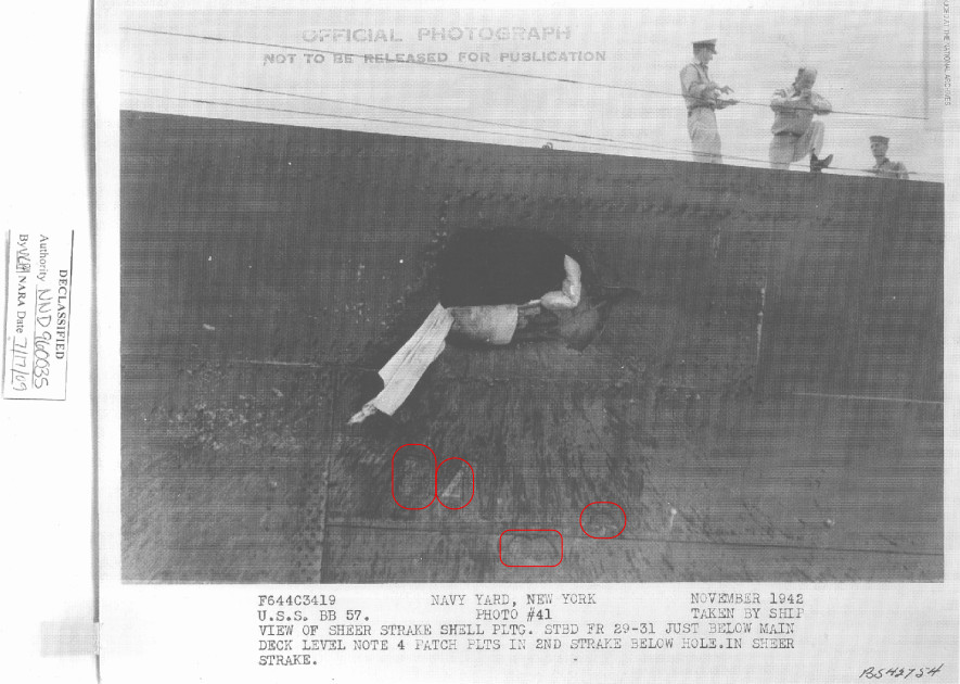
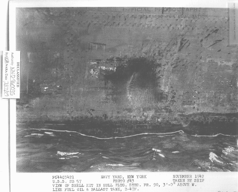
| Type | Weight | Length | Explosive charge | Fuze | Rounds fired |
|---|---|---|---|---|---|
| HE Shells | |||||
| 14" Type 0 | 1,378 lbs | 47.25" | 63.4 lbs TNA 5 | Type 91 Mod 1 | 22 |
| 8" Type 0 | 276.5 lbs | 34.64" | 18.0 lbs TNA | Type 91 Mod 1 | 6 |
| 6" Type 0 | 100 lbs | 22.5" | 6.5 lbs Picric acid | Type 91 Mod 1 | Unknown |
| 5.5" Type 0 | 83.5 lbs | 21.81" | 6.3 lbs Picric acid | Type 91 Mod 1 | Unknown |
| 5" Type 0 | 77 lbs | 32.22" | 4.15 lbs Picric acid | Type 91 Mod 1 | Unknown 6 |
| 3.9" | 28.67 lbs | 16.1" | 2.1 lbs TNA | Type 91 Mod 1 | Unknown |
| Armor Piercing | |||||
| 14" Type 1 | 1,485 lbs | 60.0" | 24.5 lbs TNA | Type 13 Mark 4 Mod 1 | 27 |
| 8" Type 91 | 276 | 35.7" | 6.85 lbs TNA | Type 13 Mark 4 Mod 1 | 91 |
| Base fuze Common | |||||
| 6" Type 04 Common | 100 lbs | 22.5" | 6.0 lbs Picric acid | Type 13 Mark 1 Mod 1 | Unknown |
| 5.5" Capped Common Mod 1 | 83.5 lbs | 21.65" | 4.4 lbs Picric acid | Type 13 Mark 1 Mod 1 | Unknown |
| 5.5" Type 2 Common | 83.5 lbs | 21.81" | 5.72 lbs Picric acid | Type 13 Mark 1 Mod 1 | Unknown |
| Incendiary | |||||
| 14" Type 3 | 1,378 lbs | 48.0" | 8.81 lbs Picric acid | Type 91 Mod 1 | 66 |
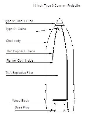
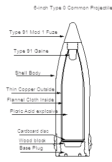
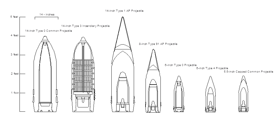
Japanese Type 0 shells were nose-fuze designs that the Japanese designated as "Common" but would be called "HE" or "HC" in most other navies. In this essay, these Type 0 shells are usually called "HE" in order to distinguish them from the base-fuze Common shells which were supplied to the light cruisers and for Kirishima's secondary battery.
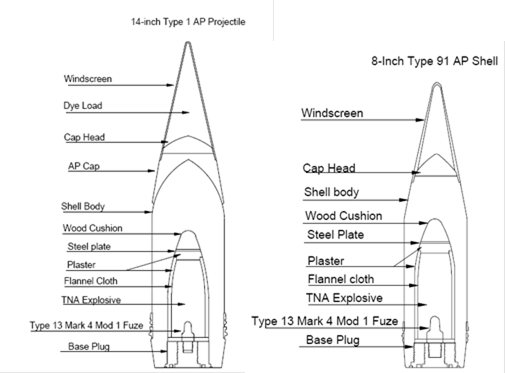
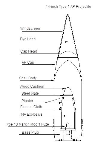
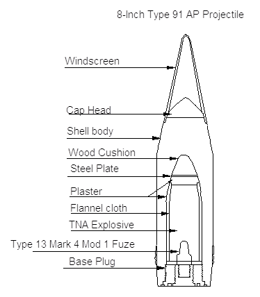
Japanese 8-inch Type 91 AP was actually more of a semi-armor piercing shell as it did not have a true AP cap but instead was designed with a small cap head. This shell was specifically designed to penetrate the homogeneous armor used on most pre-war US heavy cruisers. The 14-inch AP shell had a true AP cap and was designed to penetrate face-hardened armor. For both the 8-inch and the 14-inch AP shells, the windscreen and cap heads were designed to come off under any impact so that the flat nose of either the 8-inch shell body or the AP cap of the 14-inch shell would give a stable trajectory underwater.
The 14-inch Type 1 AP shell varied from its older cousin the Type 91 AP in that it carried a dye load and the windscreen was angled at 21 degrees vs. 23 degrees in the older shell, otherwise the two shells were nearly identical. The Type 1 AP was introduced in 1941 and Japanese records of ammunition expenditure use this designation for the AP projectiles that Kirishima fired at this battle. Dye colors assigned for the 14-inch Type 1 Mod 1 AP for the Kongō class were as follows: Kongō – Type 1 Mod 3 dye color, which was red. Hiei – No dye color – shell splashes would therefore appear as white. Haruna – Type 1 Mod 2 dye color, which was yellow. Kirishima – Type 1 Mod 4 dye color, which was either green or blue, and Kirishima's dye color at this battle was blue. 7
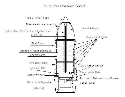
The 14-inch incendiary Type 3 shell was unique in that it had a large wood adapter at its nose covered with thin metal. The long fuze rod that ran lengthwise through this projectile normally broke if the shell struck something solid and the thin sides ripped apart so that the shell would disintegrate against even modest steel structures. This shell is also officially designated an AA shell which was its primary purpose. These were the shells that the Japanese thought had devastated the US airbase on Guadalcanal during the successful bombardment on 12 October 1942. Kirishima was loaded with this type shell for her initial salvos and fired more of this type during the battle than any other shell type, probably because they were already in the hoists and guns at the start of the battle. In order to reduce barrel wear, Kirishima's guns were initially loaded with reduced charges or else with only two bags of powder rather than the usual four bags.
The fact that his guns were loaded with Incendiary rounds and reduced charges is a fairly clear indication that Admiral Kondo was not looking for a fight with US naval units. His plan for the Bombardment Group was that it was to shell Henderson Field and that only his light forces were to deal with any US naval units encountered. When the battle first started, Admiral Kondo deliberately kept his Bombardment Group away from the action and did not bring his force to join in until he thought that the battle had been won when he saw that South Dakota had been silenced. So, the fact that he had Type 3 Incendiary shells loaded in advance represents his mission planning and does not indicate that he was surprised or caught off guard as was Admiral Abe at the earlier battle on 12 November.
The kinds of fuzes used in the Japanese shells are of interest, as the damage pattern will often show whether a particular hit was from a shell with a delay-type fuze or from one with an instantaneous fuze. The following table shows the fuzes used by the Japanese in this battle.
| Fuze | Year adopted | Weight | Location | Delay |
|---|---|---|---|---|
| Type 13 Mark 1 Mod 1 | December 1941 | 957 grams | Base Fuze | Non-Delay |
| Type 13 Mark 4 Mod 1 | June 1932 | 1,355 grams | Base Fuze | 0.4 second delay |
| Type 91 Mod 1 | January 1932 | 577 grams | Nose fuze | 0-55 second Mechanical Time Fuze |
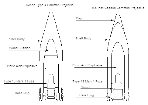
The Type 13 Mark 1 Mod 1 fuze was introduced in December of 1941 and this was used in the 6-inch and 5.5-inch base-fuzed shells. This fuze gave trouble owing to the breakdown of mercury fulminate during storage and this problem resulted in many duds during the war. 9
The Type 13 Mark 4 Mod 1 fuze was introduced in June of 1932 and was used in 8-inch and 14-inch AP projectiles. This fuze had a long delay of 0.4 seconds which allowed the shells equipped with it to have a long underwater trajectory if they fell short of their target. However, if the shell hit above the waterline, this long fuze delay also meant that the projectile was likely to pass right through a ship's structure without detonating unless it hit heavy armor.
For the nose-fuzed HE projectiles at the battle in 1942, the Type 91 Mod 1 fuze, which was first introduced in 1932, was still in use. In 1943 this fuze would be re-designated as Type 0 for shells above 8-inches in caliber and in 1944 as Type 4 Mark 1 when used with the 6-inch and 5.5-inch shells. It was discovered that all mechanical time fuzes used in these shells acted as a percussion fuze (probably due to the shoulder of the striker fracturing) against steel plates as thin as 6 mm (just under 0.25 inches). They could therefore be used against surface ships, detonating on impact, or for bombardment purposes against land targets. 9 Their official designation and primary purpose, however, was for AA projectiles, including the 14-inch caliber Type 3.
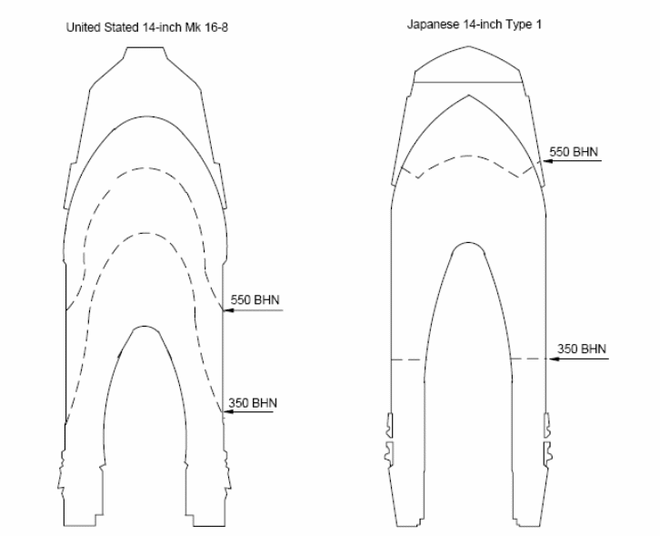
The figures below are cross sections of some of the different types of projectiles used during this battle, showing how they were constructed. 10
13. This hit, estimated to have been a 6-inch projectile, nicked the top of the starboard 20mm gun shield at about frame 17 without detonating.
There is no photograph of this damage in the damage report and a search of the USN archives did not find any. There are no inconsistencies with BuShip's estimate and, from the shell trajectory; this damage may have been caused by Kirishima's secondary battery during the 0101 to 0110 time period.
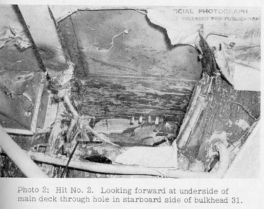
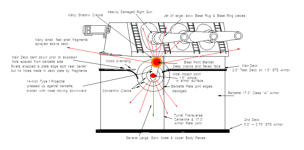
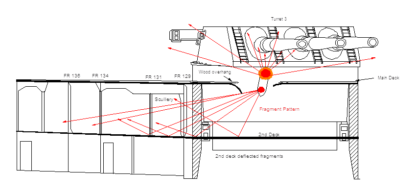
14. This projectile detonated upon impact at Frame 30 starboard blowing a 5 by 4-foot hole in the sheer strake about four feet below the main deck. The force of the detonation passes inboard and aft and blew an 8 by 6-foot hole in bulkhead 31 just below the main deck and 2 feet 6-inches inboard of the starboard side. The main deck was bulged up about 2-1/2 inches over a 5 by 4-foot area just inboard of the starboard shell and forward of bulkhead 31. The half deck was dished down about 4-inches over an 8 by 6-foot area adjacent to the starboard shell and forward side of bulkhead 31. The 42-inch ventilation duct on exhaust system H2-33-1 was blown out. Expanded metal partitions, doors, shelves and bins in AH-219-L were demolished. It is estimated that this was an 8-inch AP projectile.
15. Six holes occurred in the starboard shell plating between frames 29 and 32 just below hit 2 (photograph 1) [Ed's note – this is reproduced in this essay as Figure 8]. A seam in the shell about 1 foot above the second deck was opened between frames 30-1/2 and 32; lockers, ventilation ducts, insulation and sheathing were damaged in A-207-L; and fragments ignited a bedding bag in A-206-L and clothes in two lockers in A-207-L. Although there was no area within the ship where the reported extent of damage would indicate a point of detonation and there were no exit holes, South Dakota reported that the holes in the shell had been made by six 6-inch hits. However, from their location, the extent and nature of the damage and knowledge of the characteristics of Japanese projectiles, it is believed that these holes were made by the cap head and fragments of the windshield of the projectile of hit No. 2.
AH-219L – Ward Room Cigar Mess Stores
Exhaust system H2-33-1 – 16' ventilation duct blown out, seams torn, and all metal distorted
Gaping hole 8' through 30 lb. plate extending from main deck to 6' below main deck.
One section 4' by 8' of main deck was blown upward 4".
One Transverse 6" by 14" I beam severed and blown out from shell plating starboard to a point 8' inboard.
All intake and exhaust ventilation ducts demolished.
All metal partitions, doors, boundary angles, shelving and bins demolished.
One section of deck 4' by 6' between frames 29 and 31 starboard badly distorted.
A-206L
16" x 24" hole.
14" x 14" hole.
10" x 12" hole.
All above in shell plating 5' above deck level between frames 29 and 31 starboard.
Top seam in shell plating 1' above deck level frame 30½ blown open and rivets sheared.
3 36" x 7' panels of sheathing and insulation were blown out.
1¼" fuel ventilation line severed at shell plating.
A-207L
6' of lapped seam blown open and all rivets sheared 1' above deck [level].
3' of lapped seam blown open and rivets sheared 8' above deck.
Upper section of watertight bulkhead 31 blown open leaving a hole 9' by 6' from starboard shell plating to centerline.
2 4" by 5" T bar bulkhead stiffeners were severed 9' above deck plating.
Intake 36" circular ventilation duct system demolished.
1 12' section of exhaust ventilation duct and watertight closure demolished.
18' of 8' supply ventilation duct and brackets demolished.
4 panels of 12' by 12' insulation and sheathing demolished.
1 8' section of 3/8" x 6" x 10" I beam supporting deck overhead severely twisted, distorted between frames 31 and 33.
1 12' section of 2" fuel oil air escape piping twisted and broken.
Pea coat locker demolished.
Longitudinal I beam supporting main deck overhead fractured between frames 32 and 33.
8" by 14" hole in starboard longitudinal 10' inboard blower room, bulkhead stiffener fractured 4' above deck level.
4 triple units C clothing lockers blown open by shrapnel.
It is difficult to make them out in the photograph in Figure 8, but the original caption on this photograph notes that there are four patches on the hull below the large hole caused by Hit 2 and these have been highlighted by the addition of red ovals to this photograph. From comparing Plate 1 in the BuShips' report (shown as Figure 123 in this essay) with this photograph, it appears that one additional hole is covered up by the canvas hanging out of the left side of the Hit 2 hole. The sixth hole mentioned in BuShips' report is not shown here as it is below the lower edge of this photograph.
The first inconsistency in BuShips' report for this hit is that it concludes that the hit was made by an 8-inch AP projectile, yet the shell actually detonated on impact, which would normally indicate a nose-fuzed projectile. There is no evidence in any Japanese or USN document that the authors have found that would support a conclusion that Japanese AP projectiles of any caliber would detonate on impact on light plates. In fact, with their long fuze delay of 0.4 seconds and very small burster charge (6.85 lbs TNA), the Japanese 8-inch Type 91 AP projectile was incapable of producing the amount of damage that is documented for this impact. For these reasons, the authors of this essay have concluded that the hit must have actually been from an HE projectile.
The next inconsistency in BuShip's original report is that it has Hit 2 striking on 0.75-inches of STS steel with the six lower holes being made in HTS steel (see Figure 123). However, the Builder Plans for South Dakota show that the sheer strake where Hit 2 landed was made from HTS steel. In order to have a complete analysis in case the Builder Plans are in error, we will consider both types of steel in our damage calculations below.
The first step is to determine the caliber of the projectile that made this hit. During the battle, Atago fired six 8-inch HE shells and Kirishima fired twenty-two 14-inch HE shells. 13 Both of these used instantaneous nose fuzes, which mean that both would have exploded on impact against plates as thin as 0.25 inches thick. This means that the 0.75-inch thick outer shell of South Dakota would have been more than enough to detonate these shells on impact, regardless of whether the plate was made with HTS or STS steel.
Nathan Okun has developed an equation for nose-fuzed HE projectiles that detonate on impact with thin plates that can be used to determine the approximate amount of damage that the projectile caused to the plate:
Tphe(noADF) = (2.576 x 10⁻²⁰)(D)V5.6084COS[2(Ob2 - 45o)] + (0.156)(D) (Equation 1)
This equation computes for US Navy World War II STS and Class "B" armor plate 14 a thickness "T" where a hole of roughly caliber width will be punched entirely through by all "typical" instantaneous-impact-nose-fuzed HE projectiles that do not have an Auxiliary Detonating Fuze (ADF, used only in most World War II-era US Navy nose-fuzed HE projectiles); hence the "(noADF)" part of the label to separate it from another formula for T sometimes used with ADF-equipped shells.
This equation also applies to those World War II time-nose-fuze or VT-fuzed HE shells when the nose fuze gets crushed by a plate impact prior to the fuze setting off the shell in its normal manner (high-order detonation), as well as even applying to ADF-equipped shells under some impact conditions.
The "phe" label in this equation stands for "Penetration by HE Shell." In addition to the shell's minimum explosive filler detonation and fragmentation effects part, "(0.156)(D)," it uses the shell's impact velocity (V), angle of impact (Ob2, the impact angle Ob limited as to the values that can be used in this formula), and diameter ("caliber," D). These formulae only apply as-is to the plate directly in front of the shell that is impacted by the shell's nose. It can be used for nearby plates to the side by setting V to zero and only using the "(0.156)(D)" blast/fragmentation component.
All units in this formula are English units: T (thickness of plate) & D (diameter of projectile) are in inches, V (Striking Velocity) is in feet per second, and Ob2 (Obliquity or impact angle with zero meaning right angles to the plate face) is in degrees.
Ob2 is set equal to 45 degrees (PI/4 radians in most computer languages) whenever Ob2 is less than or equal to 45 degrees. That is, under 45 degrees from normal (right angles), obliquity has no effect whatsoever and the COSINE term is always set to 1.00. Only over 45 degrees does obliquity start to have any effect. This is because if you look at the typical explosion pattern of a HE shell, there is a narrow jet coming out the nose aligned with the centerline of the shell when it goes off, made up of somewhat larger, but still small, pieces, compared to the sideways spray. This can assist in punching a small hole in the center of the impact site, but since it is pushed into the dent of the impact when the shell detonates, the angle of impact doesn't mean much. Then there is a kind of "dead area" over a conical arc to about 45 degrees to each side surrounding the nose, with almost no fragments whatsoever in it – just a few tiny fragments of the pointed nose region. These have little damage-causing effect into the blast-induced 0.156-caliber-thick-or-less plate hole. From the 45 degree angle to roughly 135 degrees (tilted forward due to the speed of the shell a little bit), there are the mass of the small, very high speed fragments created by the detonation, most in the 70-110-degree arc ring around the projectile middle (if the projectile is stationary, otherwise tilted forward a little). This is why you have to have the obliquity change to at least 45 degrees to begin to see any difference in the effects on a plate in front of the shell nose. However, this side spray effect does not make the hole larger than the 0.156-caliber stationary projectile value, since the blast/spray effect is what was calculated to give the 0.156-caliber non-moving projectile value in the first place. Increasing the obliquity over 45 degrees rapidly causes the velocity effect on increasing the depth to go away until at angles near 90 degrees obliquity (shallow glance just barely able to set off the nose fuze) the velocity has no effect at all and the shell acts like it is standing still when it detonates, as far as penetration of the hit plate is concerned.
Weaker plates with lower quality factors – HTS has a Q(armor) quotient of 0.85 – allow deeper penetrations, inversely proportional in depth to the quality factor of that material (if there were plates BETTER than STS, then the thickness T penetrated would go down by dividing by a value larger than 1.00 (= World War II STS Q(armor)). We call this value Tmod, and it is equal to T/[Q(armor)]. Thus, if an STS plate of T = 1 inch would just give a caliber-wide hole under the impact conditions involved, then a plate made with the lower-quality HTS steel would have Tmod = 1 / 0.85 = 1.176, which means that the HTS plate would need to be 1.176 inches thick in order to have the same size hole made in it.
After calculating Tmod per the Plate Quality factor as described in the above paragraph, the diameter of the hole created by a particular HE shell when the Plate Actual Thickness is less than Tmod can be calculated with the following equation:
HOLE DIAMETER = D x [Tmod/(Plate Actual Thickness)] (Equation 2)
This formula shows that the largest possible hole is approximately 40 calibers in width for foil-thick plates of very large size. The formula shows that an 8-inch HE shell can blow a hole 319.2 inches or 26.6 feet wide in a 30 x 30 foot aluminum-foil-thickness STS steel membrane that is supported tightly around the edges, assuming that the shell hits in the center.
As plates get thicker than Tmod, the hole size created goes down rapidly, with zero hole size (merely a large dent with cracks) occurring at a plate thickness of 1.2 x Tmod. For plates thicker than Tmod, we use the following equation:
The minimum hole diameter for this equation is zero.
These equations are valid for the filler weights of typical World War II HE shells which were in the range of 6.0% to 8.99% of the total weight of the shell. 15 The Japanese 8-inch Type 0 HE shell was a modern, long, streamlined design with a length of 4.33 calibers and had a filler weight of 6.5% of the total weight which was up to 283 lbs. Therefore, this projectile falls within the valid range for these equations. 16
Turning now to the damage caused by Hit 2; the BuShips' reports states that this shell made a 5 by 4 foot hole in a STS plate that was 0.75 inches thick. To determine if this damage was caused by an 8-inch HE shell fired with a muzzle velocity of 2,330 fps which at 6,000 yards would have a striking velocity of 2,103 fps, we use the following intermediate steps which together make up the calculations for Equation 1: 17
-
(2.576 x 10⁻²⁰)(D) = 2.576 x 10-20 x 8 = 2.06 x 10⁻¹⁹
-
V5.6084COS[2(Ob2 - 45o)] = 21035.6084 x COS [2(45 - 45)] = 4.32 x 10¹⁸
-
(0.156)(D) = 0.156 x 8 = 1.25 inches
-
2.06 x 10-19 x 4.32 x 1018 = 0.89 inches
-
Tphe (noADF) = 0.89 + 1.25 = 2.14 inch thickness of STS which will result in a caliber-width hole
To find the minimum thickness of STS that ensures that no crack will be made in the plate (just a dent), we multiply 2.14 x 1.2 = 2.57 inches.
These calculations show that an 8-inch Type 0 HE shell would produce an 8-inch hole (caliber width) in a 2.14-inch thick STS plate and that a 2.57-inch thick plate would defeat this size shell, achieving only a dent. Intermediate thicknesses of STS between the 2.14 inch and 2.57 inch limits would have progressively smaller holes and shorter cracks in the plate.
Now that we have these numbers, we can calculate for the actual plate where Hit 2 struck, which was 0.75 inches thick. As we are calculating for STS plate, this means that T = Tmod which in this case was calculated above as 2.14 inches. As the actual plate thickness of 0.75 inches is less than Tmod, we use Equation 2 to determine the created hole diameter. Filling in the values for this formula:
Hole Diameter = 8 x [2.14 / 0.75] = 22.80 inches.
This is the approximate size hole that an 8-inch HE projectile would produce in a 0.75-inch thick STS plate. As can be easily seen, this estimated hole size of less than 2 feet is inconsistent with the BuShips reported hole size of 5 by 4 feet.
The above calculations were for a plate made of STS. What if the plate was actually HTS as in the Builders Plans? As HTS is 0.85% as strong as STS plating, we need to adjust Tmod per this lower quality factor:
Tmod = 2.14 / 0.85 = 2.52 inches
This means that an 8-inch HE projectile would blow an 8-inch hole (caliber width) in 2.52 inches of HTS plating (for reference, the thickness of HTS plate that would result in only a dent can also be calculated using this same quality factor: 2.57 / 0.85 = 3.02 inches).
Using the HTS value of Tmod in Equation 2:
Hole Diameter = 8 x [2.52 / 0.75] = 26.88 inches
So again, the results of the calculations for an 8-inch caliber HE projectile are inconsistent with the documented damage.
Moving now to the next larger size HE projectile that was present for the battle, the 14-inch Type 0 HE, this projectile is only 3.38 calibers long, weighs circa 1,378 lbs 18 and has a relatively small filler of 63.4 lbs of TNA (4.6%). This low filler percentage means that the Japanese 14-inch Type 0 HE shell design has an explosive burster that falls below the normal World War II HE Shell filler range mentioned above of 6.0 to 8.99% of total weight (see Footnote 16), which means that this projectile instead falls under Nathan Okun's formula for Semi-Armor Piercing (SAP) projectile types. The first step in determining the hole size that can be made by a 14-inch Type 0 projectile is to calculate what a normal World War II HE projectile would produce and then modify that result based on the ratio between the normal HE projectile and a SAP projectile.
What Nathan Okun has discovered is that a normal World War II HE projectile can blow a caliber-wide hole at a distance of 5-calibers or less from a 0.11-caliber-thick STS plate. This 0.11 figure can be used for all normal World War II HE shells, including US World War II HC projectiles that have filler percentages between 6.0 and 8.99%. This is the blast effect's only minimum distance and below this distance the still-accelerating fragments will have more hole-punching power and the caliber-wide hole in STS plate thickness steps up instantly to a constant 0.156-caliber size for a regular HE round. 19 For all SAP projectiles in the 4.0 to 5.99% filler range; these will produce a caliber-wide hole at a distance of 5-calibers from a 0.095-caliber thick STS plate. The ratio between a normal HE and a SAP round is thus 0.095/0.11 = 0.864. 20 Multiplying the results for a normal HE projectile by 0.864 will thus give the correct hole size for a SAP projectile and thus the hole size for the Japanese 14-inch Type 0 projectile. 21
As a last piece of data; at 6,000 yards, the striking velocity of a Japanese 14-inch HE projectile fired with full charges would be 2,131 fps (see Footnote 18).
With all the above information, we can now make the following calculations using the same intermediate steps for Equation 1 that were used above:
-
2.576 x 10-20 x 14 = 3.61 x 10⁻¹⁹
-
21315.6084 x COS [2(45 - 45)] = 4.66 x 10¹⁸
-
0.156 x 14 = 2.18 inches
-
3.61 x 10-19 x 4.66 x 1018 = 1.68
-
Tphe (noADF) = 1.68 + 2.18 = 3.86 inches maximum thickness of STS for a caliber-wide hole
To find the minimum thickness of STS that ensures that no crack will be made in the plate (just a dent), we multiply 3.86 x 1.2 = 4.64 inches.
Intermediate thicknesses between 3.86 and 4.64 inches of STS have progressively smaller holes and shorter cracks in plate.
Continuing now for Hit 2, if the plate struck was made from STS, then as the plate thickness of 0.75 inches is less than T we use Equation 2 which gives us:
Hole diameter = 14 x [3.86 / 0.75] = 72.05 inches
Calculating for the damage that the typical World War II HE projectile would make in HTS plating, we get:
Tmod = 3.86 / 0.85 = 4.54 inches
Using Equation 2:
Hole diameter = 14 x [4.54 / 0.75] = 84.75 inches
As the 14-inch Type 0 HE projectile has a lower amount of explosive filler than the average World War II HE projectile, the size of the holes needs to be reduced by the SAP adjustment factor of 0.864 calculated above. This means that the hole created in 0.75-inch thick STS plate would be:
72.05 x 0.864 = 62.05 inches or just over 5 feet
And the hole created in 0.75-inches thick HTS plate would be:
84.75 x 0.864 = 73.22 inches or about 6 feet
These figures are far closer to the 4 x 5 foot exterior hole and the 8 x 6 foot interior hole in bulkhead 31 as documented by BuShips. This means that the 14-inch Type 0 HE projectile is far more consistent with the damage described by BuShips and is the best conclusion as to the projectile that caused this damage.
The timing of this hit is also important. When Kirishima re-opened fire at 0100, Lieutenant(jg) Michio Kobayashi, who was on her bridge at the time, thought that he saw Kirishima hit South Dakota in the area of Turret I. 22 This damage confirms that Lieutenant(jg) Michio Kobayashi did indeed witness one of Kirishima's projectiles impacting very close to turret one.
The next question then is what made the holes below Hit 2? First of all, BuShips' report and South Dakota's action report have significant disagreements as to what was the kind and extent of the damage to the hull below Hit 2. South Dakota's Enclosure D lists three holes of 16 x 24 inches, 14 x 14 inches and 10 x 12 inches in the hull at compartment A-206L. 23 In contrast, BuShips reported finding six holes in this area of the ship's hull and that all of these were much smaller than the ones reported by South Dakota. 11 Plate 1 (shown as Figure 123 in this essay) from BuShips' report shows the six holes below Hit 2, and these are listed on Plate 1 as being five holes of 6 x 6 inches plus an additional hole that is not dimensioned but appears to be somewhat larger than the other five holes. Finally, looking at Figure 8 above, one can see four patches on the ship's hull (apparently applied shortly after the battle) that are covering up the damage in this area. Also in the BuShips' report, there is an assertion that although the ship's crew had concluded that these holes were made by 6-inch shell fire, the BuShips investigators had determined that there was no area within the ship where the extent of the damage would indicate that a shell had detonated inside the ship's hull and that there were no exit holes through the ship's structure. For these reasons, the BuShips investigators came to a different conclusion that no additional shells were involved and that these holes were the result of the cap head and windscreen from the AP projectile that they had concluded had made Hit 2.
One thing that is almost certain about these holes is that BuShips' assertion that they were made by the cap head and windscreen from an 8-inch AP shell cannot be correct. Our estimate is that Hit 2 was made by a HE projectile, so there would be no cap head or windscreen from this projectile to make these holes. Even if Hit 2 was made by an 8-inch Type 91 AP projectile, the 5-inch diameter cap head and light-weight windscreen of that projectile could not have made more than a single hole each of the size found by BuShips.
The authors and editor of this essay had a long discussion on the causes of these small holes, but in the end we have concluded that the BuShips investigators were probably on the right track and that these holes were most likely the result of fragments that were thrown out by the 14-inch Type 0 HE projectile that made Hit 2.
Finally, note that Hit 2 made a larger hole in the interior bulkhead #31 than it did in the outside hull plate. This bulkhead is listed as being 2.5 feet inboard of the hull and parallel to it. Assuming that this inboard bulkhead is made of thin steel of about 0.25-0.5 inch thick HTS or regular construction steel (Q = 0.7 or so), then it is still within the contact blast distance with the blast wave accelerating the fragments of the HE shell (not a lot of projectile fragments in the forward direction, of course) and, to a lesser extent, the fragments of the 0.75-inch HTS 5 x 4 foot hole from the hull plate (which would have made lots of plate fragments). These all hit bulkhead 31 in a widening cone of blast and fragments, making a larger pattern of fragment impacts than in the hull plate. Since this inboard bulkhead is thin enough for all of the rather few forward-directed fragments of the projectile and of the many 0.75-inch HTS hull plate fragments to punch through (this is only for this first spaced plate, though, since this uses up almost all of their penetrating power, with very few fragments capable of penetrating a second spaced plate), it gets plastered and riddled over a wide area and then the blast (reduced somewhat by the energy lost in puncturing and accelerating the pieces of the outer 0.75 inch thick hull plate but still with a lot of "overkill" energy to punch through such a thin second spaced plate) hits it, tearing it open even wider as the fragment holes unzip like stamp perforations and form narrow tears radiating outward for several feet to all sides. Also, as in Hit 4, the narrow air gap concentrates the forward-directed and even some of the side-directed (that passes through the wide outer hole) concussion and blast pressure, further enlarging the hole. This is why that second inner hole is wider than the outer impact hole. Trying to do a detailed calculation on this inner hole is not really possible, as the variables are many and indeterminate. The above discussion is meant as an explanation of the chain of events that created this hole.
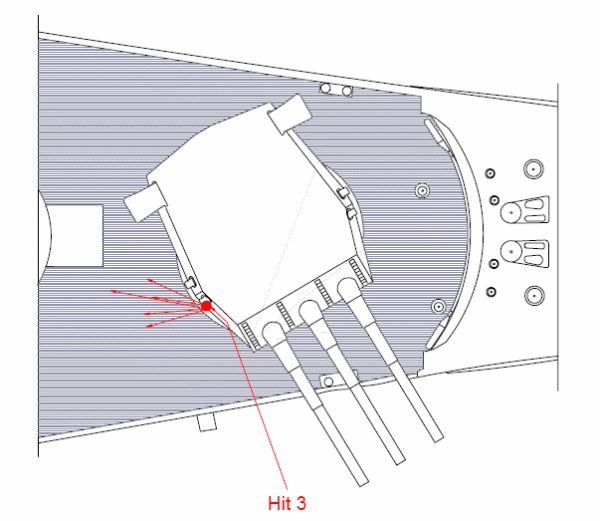
16. The starboard side of Turret I was struck a glancing blow by a projectile, probably 6-inch, which exploded on the starboard sight port. The hinge on the sight port was bent and the closing device on the port was rendered inoperative. Seven strakes of wood deck planking between frames 44 and 48 were badly splintered by fragments.
A shell struck starboard side plate #1 turret approximately parallel passed through the 25 man life raft* and exploded on the starboard sight port. Hinge on sight port bent and distorted. Closing device on port inoperative.
7 strakes on wood deck planking splintered and gouged by shrapnel between frames 44 and 48, main deck 4' to 6' inboard of shell plate.
*Total of five (5) balsa wood life rafts destroyed, about the ship.
There are no inconsistencies between the reports for this hit and it probably was a 6-inch shell from Kirishima. Another possibility is a 5.5-inch shell fired by one of the light cruisers during the time between 0048 and 0054. The specific time of this hit is unknown and the exact bearing of Turret I at the time of the hit is also unknown, but it was certainly trained to starboard in the direction of the Japanese ships as shown above in Figure 10.
17. This hit struck between frames 46 and 47 about one foot above the third deck. It penetrated longitudinal torpedo bulkhead No. 2 and detonated on the 12.2-inch longitudinal armor bulkhead about 2 feet 2 inches above the third deck. The armor was not indented, but the projectile left a black circle about 6 inches in diameter within a partial black ring about 8 inches in diameter on the face of the armor. The force of the explosion blew the third deck down 3-1/2 inches over a 15 by 30 inch area and fragments penetrated the third deck between bulkheads No. 2 and the longitudinal armor bulkhead in two places. Torpedo bulkhead No. 2 above the third deck was blown outboard between frames 46 and 47 by the force of the explosion. The following tanks were reported flooded as a result of the hit; A-11-F, A-21-F, A-23-F, A-33-F and A-39-F. Although it was not mentioned in the report, A-27-V probably flooded also.
18. This projectile most likely landed short of South Dakota and was about to ricochet as the hit was below the waterline and the projectile was rising. From the black circles which the projectile left on the armor, it is estimated that this was an 8-inch AP projectile.
South Dakota's action report simply lists this damage as a 12-inch hole located 2.5 inches below the waterline at Frame 46. 26
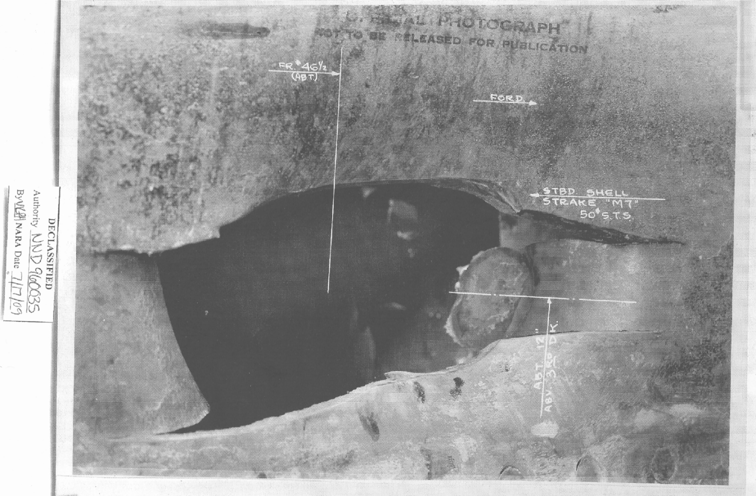
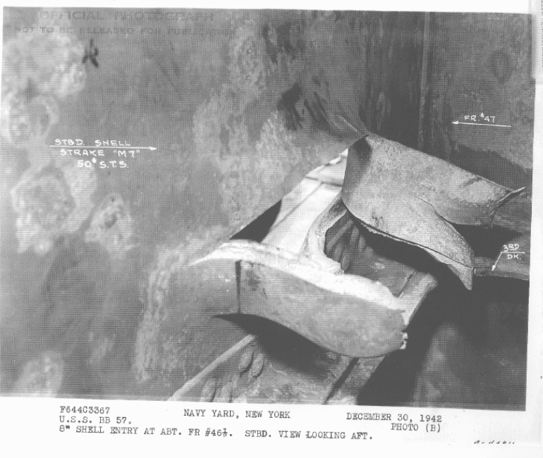
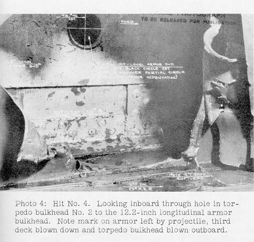
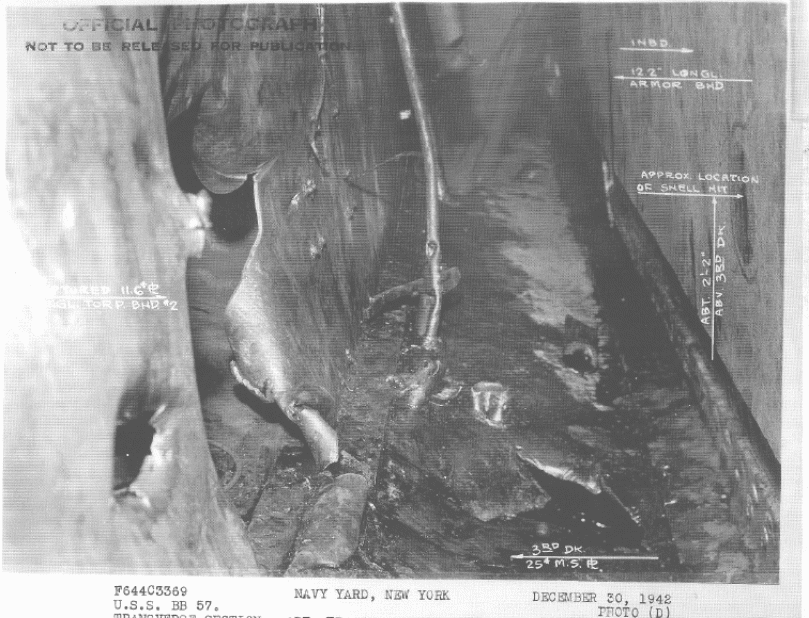
The flat face of the shell body also left a mark on the outer shell as seen to the right side of the exterior hole in Figure 11. This flat face is unique to AP shells and the 12-inch hole plus the circular scar on the main belt as seen in Figure 11 really helps with the identification of this shell type.
Figure 12 also shows a circular scar on the end of the extrusion closest to the camera which was caused by the flat head of the AP projectile.
Figure 14 shows how this projectile came in from the left through the Second Torpedo Bulkhead and then struck the Main Belt on the right.
Note that Figure 13 and Figure 14 also show that the main belt was not dented in any way; there is mainly just a "scuff" mark on the armor plate.
There are no inconsistencies with this damage or with BuShips' estimate of an 8-inch AP projectile. 27 Although this shell was slowed down by its underwater trajectory, it still had enough velocity remaining to penetrate the torpedo defenses and reach the main belt but not enough to significantly damage the plate.
The 8-inch AP projectile punched a rectangular hole out of the 1.25-inch STS outer hull which implies that it must have hit at a significant horizontal obliquity, but with minimal angle of fall. The windscreen was smashed flat and broken up by the impact with the outer shell, but the cap head remained on the projectile nose until it went completely through and even then did not have time to move much before the projectile eventually terminated its flight up against the belt armor. The projectile with the cap head still "riding" on its nose then punched through the HTS upward extension of the first internal anti-torpedo bulkhead and then it hit the main belt, where it destroyed itself, leaving only a 5-inch wide black circular disk on the face of the belt plate with an 8-inch wide narrow black ring surrounding it. What made the black color is unknown, but it might have been due to the impact shock of the 5-inch diameter flat nose under the crushed cap head and/or transmitted blast shock of the shell detonation removing paint and a very thin surface layer of the cemented part of the plate face, exposing the dark carburized layer that makes up about 1 inch of the plate thickness. The 8-inch ring might be due to the thick 8-inch diameter base hitting the armor after the projectile body in front of it had been destroyed. Other than this, the belt plate had no damage whatsoever.
Note that the hole in the upward extension of the anti-torpedo bulkhead is about 35 to 40 inches wide and was almost exactly in the center between two of the ship's vertical ribs, so nothing was there to modify the size of the hole in the horizontal direction. This portion, which is above the main 0.75-inch HTS anti-torpedo bulkhead, is thinner at 0.625 inches thick HTS. This plate was possibly still wrapped around the base of the projectile when the nose hit the belt armor and the shell detonated by impact shock. The internal cushion would not prevent such a detonation when the front of the shell shattered and the damage cut into the explosive cavity and the shell seems to have fully detonated high order, though this is not absolutely assured.
We can use Equation 1 from Hit 2 to calculate the hole size here. As mentioned in that section, "V" in Equation 1 is equal to zero when calculating damage for any plate other than the plate that actually sets off the nose fuze. This greatly simplifies the calculations for an HE shell:
Tphe(noADF) = (2.576 x 10⁻²⁰)(D)V5.6084COS[2(Ob2 - 45o)] + (0.156)(D) (Equation 1)
= 0 + 0.156 x 8 = 1.25 inches
As the torpedo bulkhead is thinner than this value, we use Equation 2 to calculate the hole size as follows:
Hole Diameter (for an HE shell) = 8 x [1.25 / 0.85 / 0.625] = 18.82 inches
This shell, with only about 2.5% TNA filler (the rest of the 4% cavity was filled with inert cushion material), which makes it an AP-type shell. This reduces the hole-size calculation by 0.08/0.11 = 0.727:
Hole Diameter (for an AP shell) = 18.82 x 0.727 = 13.68 inches
Which is much smaller than the actual hole size of 35 to 40 inches.
What gives?
The only thing I can see is the fact that the blast is contained in the narrow space between the thin anti-torpedo bulkhead at its base, with the hole it made being partially blocked by the projectile base, and the essentially infinitely thick and rigid face-hardened belt plate in front of it. The blast pulse, which in a open area would only push up against the thin plate once as it moved outward from the projectile, is now confined in a rather narrow space only about 36 inches deep where it can expand sideways, but not forward or backward. This containment and the impact and super-sonic detonation blast shockwaves in the air reflecting from the belt plate into the thin plate would greatly increase the maximum size and duration of the blast pressure pulse on that thin plate, coming from the inside of the space between the two plates backward toward the projectile base. Note that the thin plate edges are all bent outward away from the belt, indicating the pressure was from the inside outward. This seems to have increased the damage diameter by almost 300% over what would normally be expected for a Type 91 AP projectile detonating on a 0.625-inch HTS plate.
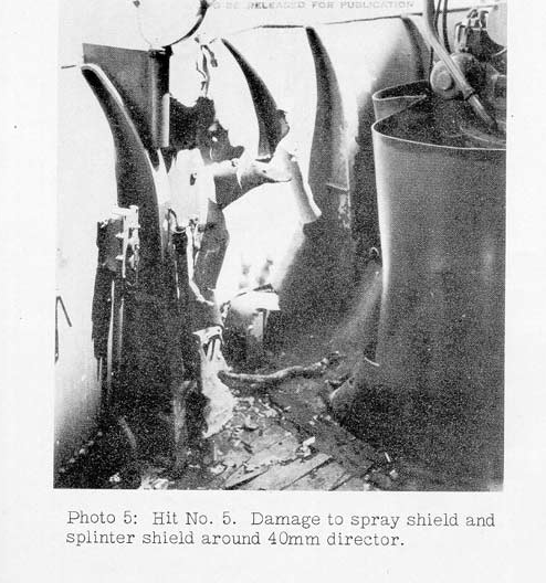
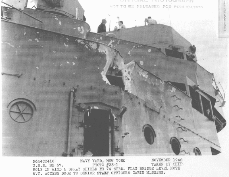
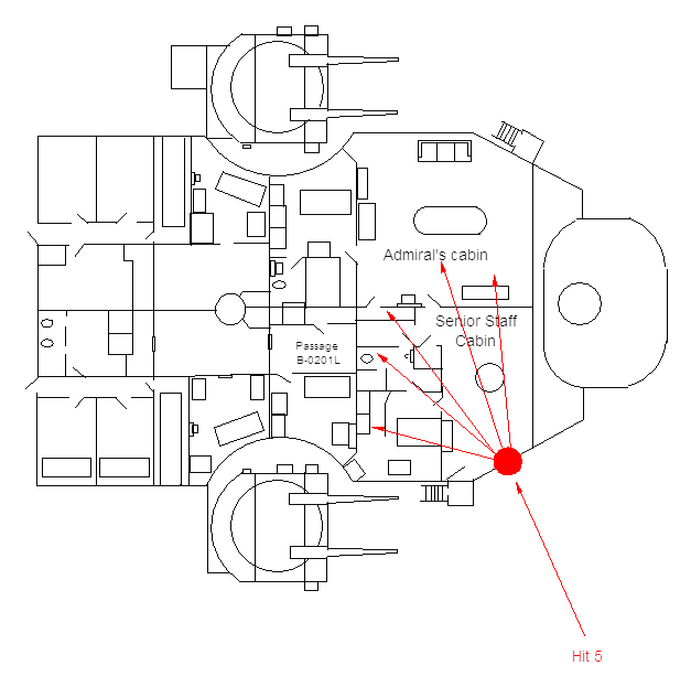
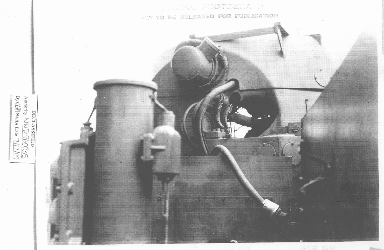
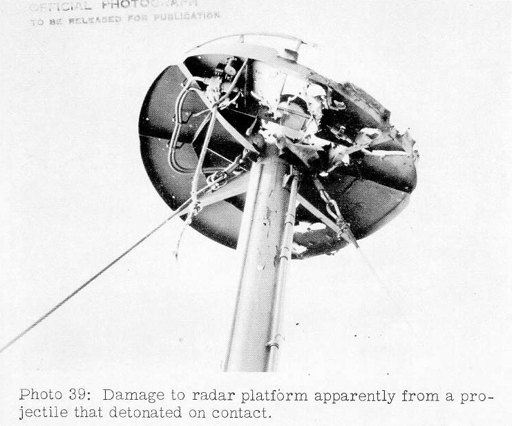
19. The wind and spray shield at Frame 74 starboard on the flag bridge level was hit by an estimated 8-inch projectile that detonated on contact. The 10-pound STS splinter shield around the starboard 40 mm director was badly buckled and holed and the 40 mm director was extensively damaged. Fragments from this projectile penetrated the deck of the flag bridge in the vicinity of Frame 74 and the watertight door between the signal bridge and signal shelter. One fragment gouged a hole 3 inches in diameter to a depth of 3/4 inch in the 1-1/2 inch STS bulkhead of the signal shelter. Other fragments blew downward and sprayed the first super structural deck between frames 66 and 72 starboard and penetrated hatch 01-07-1 in eleven places. On the navigation bridge fragments from this projectile penetrated the spray shield and the starboard longitudinal structural bulkhead in two places and the deck in three places near Frame 75. Extensive blast damage was sustained by metal joiners, ventilation ducts, aluminum bulkheads, and metal furniture in the vicinity of the hit. Three glass panels on the flag bridge were broken by blast or fragments and the operating mechanisms rendered unserviceable.
The information on this hit covers multiple pages within South Dakota's action report. Damage extended from the 1st superstructure deck level to the Navigation deck level. The only photograph in BuShips' report (shown above as Figure 15) is of fragment damage to the 40 mm director, but does not show the point of impact. However, a search of the archives did turn up a photograph of the entry hole as seen below in Figure 16.
[Flag Bridge level]
8" shell struck the upper edge of bulkhead plating of spray shield and Flag Bridge, Frame 72 1/2 starboard, resulting in the following damage:
Shrapnel blew downward penetrating wood and steel deck on first superstructure deck starboard between frame 66 and 72, approximately 45 holes ranging in size from ½" to 5".
Cover of watertight hatch 01-70-1. 11 small holes ranging from ½" to 1 ½".
Two steel ladder rungs on longitudinal bulkhead 70 starboard cut out and broken.
Light lock bracket to door 01-72 loading from 1st superstructure to Captains cabin broken off.
Senior staff officer's cabin, starboard longitudinal structural bulkhead and stiffeners between frame 72 and 74 buckled inboard approximately 3" over entire area. Two aluminum battle ports, frame 72-73 broken beyond repair. Metal book case 4' x 6', doors, hinges, and shelving distorted beyond economical repair. Supply ventilation duct torn and crushed. Metal joiner door and frame to linen locker broken. Metal joiner door access from passageway to stateroom bent and distorted beyond repair. 3' x 6' panel of after inboard divisional bulkhead blown out. Metal joiner door and frame to Admiral's cabin blown out. Metal joiner door access to first super structural deck blown out. Metal joiner door and frame between cabin and stateroom blown out. The transverse aluminum panel bulkhead between cabin and stateroom was blown out. Transverse aluminum panel bulkhead between cabin and bath blown out. Senior staff officer's stateroom, metal joiner door with full length mirror distorted and buckled. Confidential safe blown from bulkhead. Metal book case distorted and blown from bulkhead. 6' section of 1½" voice pipe leading to Flag Plot broken off at joint. Door of #1 Wardroom locker torn from hinges. Longitudinal aluminum panel division bulkhead between stateroom and bath blown out. Aluminum panel division bulkhead between bath and passageway completely blown out. Drainage valves to wash basin broken. 25
FLAG BRIDGE LEVEL
Watertight access door 03-79, to B-0305E is badly distorted.
6' section of exhaust vent duct, compartment B-0305E, completely blown out.
1 section vent duct leading to pre-heater supply system 03-79-1 blown out.
Sides, drawers, and fastenings to signal bridge desk torn and distorted beyond repair.
Hole, 12" x 36" in outboard corner of starboard flag bag.
3" fragment hole 3' above bottom starboard end.
Light metal tissue blown out.
5' section of 4" drain line severed at frame 83, starboard.
2" drain line pierced and severed by shrapnel, frames 72 and 73 starboard.
1 1/2" voice tube, starboard alidade to conn, severed at frame 73.
6' square of wind and spray shield and stiffeners at frame 73 starboard demolished by salvo.
1/4" STS splinter shield around the starboard 40 mm director at frame 74 demolished
40 mm director demolished.
5 square feet areas of wood deck planking and margin steakes [sic] splintered and broken. Steel deck plating beneath wood deck in this area penetrated by several pieces of shrapnel.
1 1/2" inch STS armored signal shelter bulkhead starboard is gouged to a depth of 3/4" over a 3" circular area.
Watertight access door, access from signal bridge to signal shelter frame 71 starboard, pierced in 6 places by shrapnel. Holes ranging from 3/4" to 4" to 4" [sic]. 3/8" heat treated glass panel blown out.
3 36" x 42" heat treated glass windows broken. Raising and lowering mechanism broken and distorted. Unserviceable. Frame 68 starboard.
Metal joiner door leading from signal shelter access to flag plot blown inward and distorted. Frame 72, centerline.
Hood for starboard signal light blown from fastenings and broken.
Doors to signal locker desk broken and distorted. Frame 79, centerline. 28
The damage continued on up to the Navigation Bridge level:
NAVIGATION BRIDGE LEVEL
Wet and dry bulb thermometer casing demolished, frame 77 stbd.
4" hole in wind and spray shield 3' above deck level at frame 75, starboard.
1 6" hole, 1 3" hole and 1 4" hole in deck from shrapnel at frame 75 starboard.
1 3" and 1 2" shrapnel hole located in longitudinal structural bulkhead 1' above deck level at frame 75, starboard.
4" hole in spray shield 3' above deck at frame 75, starboard. [Ed's note: This may be a duplicate of above entry.]
1 3" and 1 2" shrapnel hole in longitudinal structural bulkhead 1' above deck level at frame 75, starboard.
1 6" shrapnel hole in circular base of starboard alidade.
1 section 3' by 5' in spray shield between frames 70 and 71 starboard blown inboard and distorted.
Swivel base scat (mess stool) on spray shield at frame 72, starboard demolished.
Watertight door access from pilot house to catwalk bent and distorted at frame 71, starboard.
Pipe rail and fittings supporting canvas windbreaker around catwalk port and starboard broken and unserviceable. Canvas windbreaker blown out.
20" x 36" heat treated glass panel in watertight access doors leading from catwalk to Navigation Bridge, port, blown out.
10" x 20" hole in deck overhead in upper section of longitudinal structural bulkhead at frame port. (Chart House)
6' x 8' panel of aluminum dividing bulkhead between Captain's sea cabin and Navigator's sea cabin demolished.
1 section of longitudinal panel bulkhead in navigation washroom and water closet blown out.
[Illegible] section of 4" ventilation duct broken off at the joint near washroom and water closet.
Natural exhaust ventilation closure for chart house to atmosphere at frame [illegible] port blown out.
1 4" shrapnel hole in wind and spray shield 4' above the deck level at frame 74 port.
This shell is certainly a nose-fuzed projectile. The original crew estimated it to be an 8-inch projectile and this appears to indeed be the case. Despite the level of description in South Dakota's Action Report about this hit, there was not a good sense of the hole it produced in the exterior bulkhead of the Flag Bridge until I found the photograph in Figure 16 which shows about a six foot hole in the Flag Bridge windscreen. The thickness of the exterior bulkhead on the Flag Bridge windscreen is 0.25 inches of STS steel. This projectile appears to have detonated on impact and blasted inboard into the Senior Staff Officer's stateroom and Admiral's cabin. The door to the Senior Staff Officers cabin was blown off due to blast overpressure from Turrets I and II, and the fact that it is missing is not associated with the 8-inch HE projectile hit above.
This is an actual case of a Type 91 Mod 1 fuze detonating on a 6 mm thick plate just as the Technical Mission Report documented that it would. 30
The steel used for the superstructure was more likely to be HTS and not the STS that is listed in her original report. Using the figures established in Hit 2, an 8-inch HE projectile would produce a caliber size hole in 2.52-inch thick HTS plate. Using Equation 2 for the 0.25-inch HTS plate found here:
Hole Diameter = 8 x [2.52 / 0.25] = 80.64 inches
This calculated hole diameter is about 6.7 feet, which is close to the 6-foot hole size documented in the report.
To confirm this, we now look at the damage a normal World War II 14-inch HE projectile would have produced. This size shell will make a caliber size hole in a 4.54-inch thick HTS plate. We then can use Equation 2 as follows to calculate for the 0.25-inch thick HTS plate:
Hole Diameter = 14 x 4.54 / 0.25 = 254.24 inches or 21 feet
Even taking into account the smaller explosive filler of the 14-inch Type 0 HE projectile; 254.24 x 0.864 = 219.66 inches or 18.3 feet, this size projectile would have resulted in the bulkhead completely disappearing! Clearly, this hole was not made by a 14-inch projectile and the best estimate is an 8-inch Type 0 HE projectile.
The large number of shell fragments of relatively small size for this hit is typical of a HE shell due to the large cavity and thinner sides of that kind of projectile. The only heavy cruiser to fire Type 0 HE projectiles was Atago as Takao fired only AP ammunition during this battle. Atago was the last heavy cruiser to open fire at 0103 and there is only a brief period of time during which she is ahead of South Dakota, as she was in the lead of the Japanese formation. Since Atago was part of the bombardment group, she may very well have been loaded with Type 0 HE shells for her first salvo. Her ammunition report says that she fired a total of six HE shells during the battle. 31
20. The 10-pound STS splinter shield was hit at frame 74 about two feet above the house top deck. The projectile penetrated the 60-pound STS foundation of No.1 five-inch secondary battery director, severed the center column, passed out through the port side of the director foundation and the port splinter shield at frame 75 without detonating. A small electrical fire started and ignited some life jackets. It is estimated that this was an 8-inch AP projectile.
[From "Chronological Log of the Battle" section of Action Report]
0102 ... Sky Control out. S.B. director 1 hit and out of commission
1 18" hole in ¼" STS splinter shield two feet above deck level at frame 73 starboard.
1 36" by 48" hole in ¼" STS splinter shield at frame 74 port 3' above deck level.
1 shell hole 10" by 16" through 1½" STS circular foundation plate of #1 5" director at frame 73 starboard, 6" above bottom level.
1 12" shell hole through 1½" STS circular base of #1 5" director at frame 73 port, 6" above deck level.
Center column structure and bounding angle of #1 5" director completely demolished. 34
Secondary Battery Director #1 was struck by an 8" projectile which entered foundation about one foot from deck, starboard side, passing through center column and out port side. All cables were out. Roller path believed to be completely out of alignment. 35
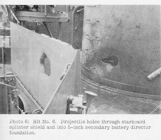
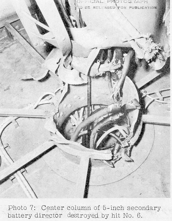
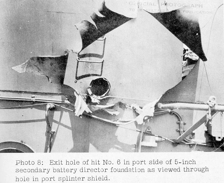
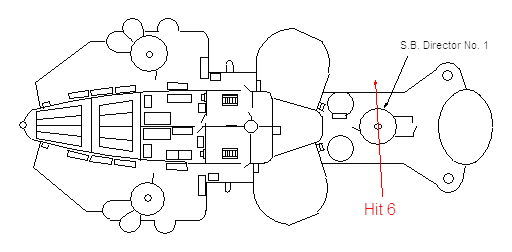
There is not any inconsistency with this estimate of the shell being an 8-inch AP projectile. The reported 10-inch and 12-inch holes through the circular foundation eliminate any possibility this was from a larger caliber. The hit is documented in South Dakota's action report as occurring at 0102 and this is also the time when Takao opened fire. 36
21. The 30-pound STS bulkhead of the 1.1-inch clipping room was pierced by a projectile that passed through and out about 6 feet above the housetop at frame 78-1/2 and detonated over No. 4 1.1-inch quadruple mount. Three fragments penetrated the 15-pound STS splinter shield around the mount exploding the ready service ammunition on the shield and six fragments pierced the deck within the working circle of the mount. The mount itself was badly damaged by fragments. Within the 1.1-inch clipping room the centerline beam was severed, the overhead blown open, ventilation ducts crushed and insulation badly damaged. Several 1.1-inch clips exploded and ignited life jackets of dead and wounded men. The sprinkling system was cut in three places and 75 1.1-inch clips were destroyed. From the size of the hole it is estimated that this hit was an 8-inch AP projectile.
South Dakota's time line in her action report recorded this as her first hit as follows:
[From "Chronological Log of the Battle" section of Action Report]
0049First hits sustained. (?) [sic] Probably 1.1" clipping room in foremast structure.
Increased speed to 27 knots.
WASHINGTON asked "Are you alright", replied "Everything seems okay."
[From list of Fire damage]
Passage B-319T, fire reported to Repair II as being in 5" handling room. Passage was full of smoke with a red glow. Investigation revealed two burning life jackets ignited apparently by blast through ammunition hoist from clipping room B-0502M, which had an 8" shell pass through it with the resulting explosion of 1.1" clips and fire. Passage was sprayed with fog nozzle. The Jackets were extinguished with C02. This fire was small but potentially the most dangerous we had as it entered into the armored spaces.
...
Clipping room B-0502M. Repair party 1. Fire was out when repair party arrived. After shell passed through this clipping room, several 1.1" clips exploded. Powder was burning in forward port corner and life jackets of deceased and wounded men burning. Jacosevich, Stephen, S2c entered the clipping room with CO2 and extinguished the fire. 38
[From list of damage in Enclosure D]
HOUSETOP LEVEL
10" hole in STS structural bulkhead in 1.1" magazine and clipping room 6' above deck level at frame 78 starboard.
18"-24" shell hole in STS structural bulkhead in 1.1" magazine and clipping room 6' above deck level, frame 78 port.
1-6", 3-7" and 1-4" shrapnel holes through 3/8" STS splinter shield around 1.1" quad No. 4, frame 78 port.
6 shrapnel holes in steel deck plating within circular area of 1.1" quad No. 4. Average size of holes 4".
Battle telephone box for quad 4 demolished.
1.1" CLIPPING ROOM, B-0502M
3' section of longitudinal centerline deck overhead beam 6" by 12" severed and demolished, frame 78-79.
All sheathing and insulation demolished.
5 sections of magazine stowage racks cut, distorted, and unserviceable.
3 sections of 3/4" pipe sprinkling system severed and demolished.
Bulkhead stiffeners and beam knee severed and demolished.
Bounding angle and deck overhead blown open and all rivets sheared.
1 ½" shrapnel hole in flame tight access door.
Vent ducts supply for B-0601L crushed and vent ducts crushed and broken frame 81 port B-103L.
1 2' square section of insulation sheathing from longitudinal bulkhead at frame 82 port destroyed. 34
GUNNERY DAMAGE
Machine Gun Battery
Clipping room 3 and 4
One and possibly two projectiles passed through forward end of clipping room, causing extensive structural damage. Sprinkling lines were out and 75 clips destroyed. 39
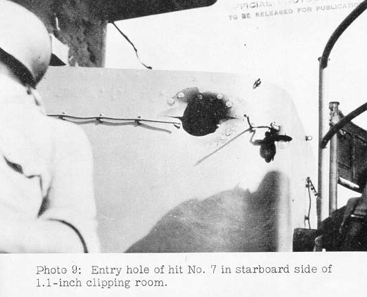
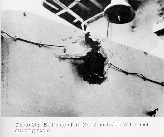
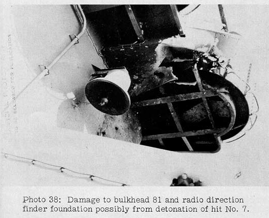
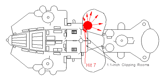
This hit is documented as being the first one received by South Dakota and occurred at 0049. At this time, the heavy cruisers are 11,000 yards off South Dakota's bow heading west and have not yet even spotted South Dakota. This makes BuShips' estimate of an 8-inch shell impossible. It also could not have come from any of the destroyers as they were equipped with only nose-fuzed projectiles which would have exploded on impact, which this shell did not, indicating that it was a base-fuzed projectile. The light cruisers Nagara and Sendai were engaged with South Dakota at this time and thus this hit is most likely a 5.5-inch capped Common projectile or a base-fuzed 5.5 inch Type 4 Common projectile from one of them. The shell detonated as it exited the port side, blowing the larger hole in the second bulkhead. The shell trajectory being almost straight through the compartment matches Sendai's position at 0049 which was abeam of South Dakota while Nagara was slightly aft of her beam.
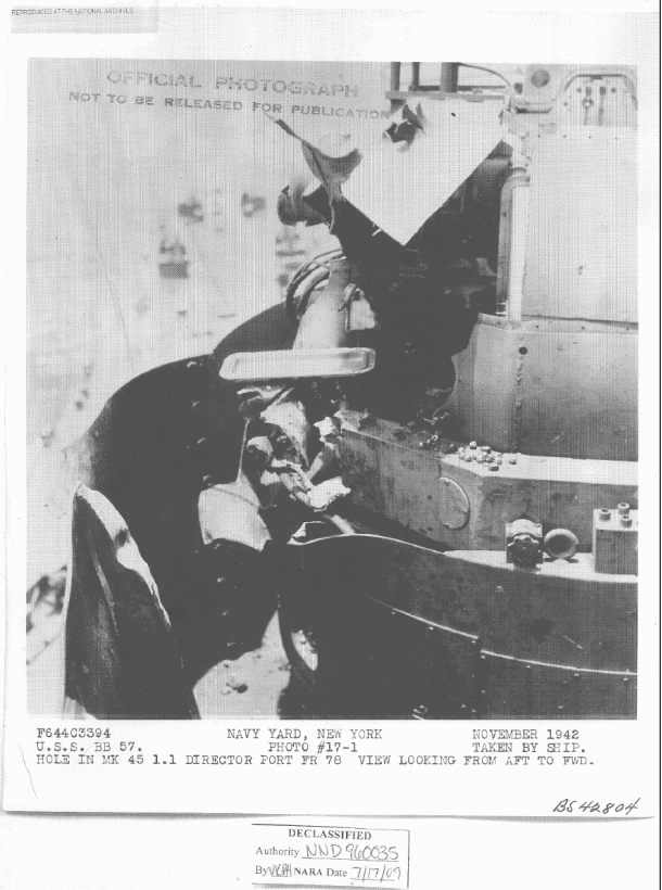
22. This projectile, probably 8-inch, hit the Mk. 45 1.1-inch director on the third level above the house top at frame 79. It ripped through the director apparently without exploding.
Mark 45 1.1" director demolished. 40
A 5.5-inch base-fuzed projectile fired by the light cruisers may be a better estimate for this hit. An 8-inch shell should have caused much more damage to the director due to the nose coverings flattening out on impact. This hit may have occurred at a similar time as Hit 7, which struck just below this level and which would have occurred before the Japanese heavy cruisers opened fire. The dimensions of the damage for Hit 8 are not recorded, so it is difficult to make an accurate estimate for this hit.
23. The wind and spray shield around air defense forward at frame 79 had one hole on the starboard side and two holes on the port side. It is possible that the two holes on the port side were caused by different projectiles. However, it appears more likely that the cap head of an 8-inch AP projectile broke off upon hitting the starboard side of the windshield and made the second hole in the port side of the windshield. Apparently the projectile or projectiles did not detonate.
Forward centerline section of wind and spray shield around search radar demolished. 3-17" holes. 41
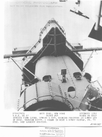
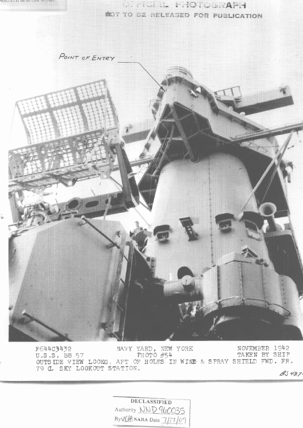
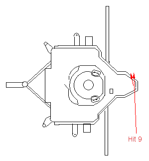
In the left foreground of Figure 29 is the radar antenna atop Secondary Battery Director Number 1. This is not the search radar mentioned above as being damaged by Hit 9. This search radar antenna is not visible in the above two photographs.
This damage was documented in South Dakota's report as occurring around 0102, so BuShips' estimate of an 8-inch AP projectile is possible. This is probably the best estimate due to the 17-inch entry and exit holes through the 0.25-inch STS plate. The cap head flying off estimate by BuShips also makes sense and accounts for the second exit hole. Takao opened fire at about this time, so she may be responsible for this damage. 42
24. A 10-inch hole was pierced in the starboard longitudinal structural bulkhead at frame 82 about 7 feet above the house top. The centerline bulkhead had a 10-inch hole about 30 inches above an 8-inch hole at frame 83. The port longitudinal structural bulkhead had a 10 inch hole about 6 feet above the first level above the house top at frame 84 and a 10 inch by 3 inch hole at the deck level. These holes were reported to have been caused by an 8-inch and a 5-inch projectile. It appears more probable that an 8-inch AP projectile cap head broke off the projectile upon penetrating the starboard bulkhead and made a second hole in the center line and port bulkheads, while the intact projectile made only one entry hole in the starboard bulkhead. The access ladders to the second level above the house top were damaged, and ventilation ducts demolished, but there is little evidence of a detonation associated with this hit.
6TH LEVEL
1 10" shell hole through structural bulkhead and bulkhead stiffener, 6' above deck level, frame 82 starboard.
Web of I beam frame 83 twisted and distorted 6' inboard of starboard side.
10" x 8" hole in centerline bulkhead, frame 83. Arch reinforcement twisted and broken.
Gas radar tube fractured.
Access ladder from 06 to 07 level demolished.
Vent duct exhaust peppered with small bits of shrapnel.
Coil spring tensioning device and brackets for watertight hatch 07-84-1 demolished.
Natural vent exhaust duct through forward transversal structural bulkhead in #1 radar storeroom demolished.
Supply vent duct demolished in B-103L, 06 level.
Access ladder from 06 to 07 level demolished.
Tensioning device and brackets for watertight armored hatch 07-84-2 twisted and inoperative.
3/4" circulating cooling water pressure gage and booster pump severed and demolished.
W.R.S.R. 44 0601. 2 1" holes in steel battle port.
10" hole 6' above deck level and frame 83 port.
1 bulkhead stiffener 8" torn and distorted throughout length.
Shrapnel hole 10" x 3" at deck level.
Insulation and sheathing on port longitudinal bulkhead entirely demolished.
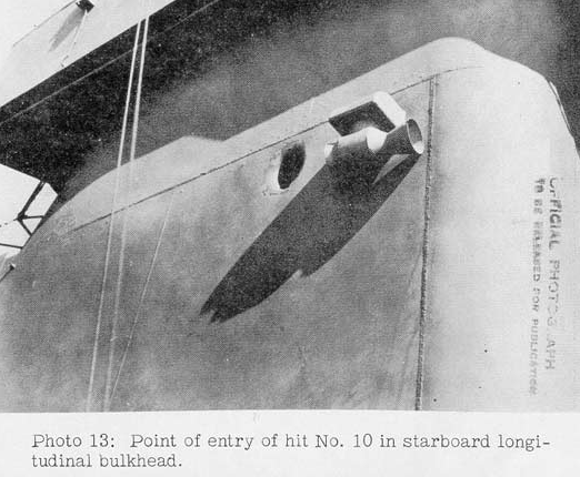
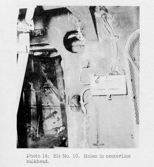
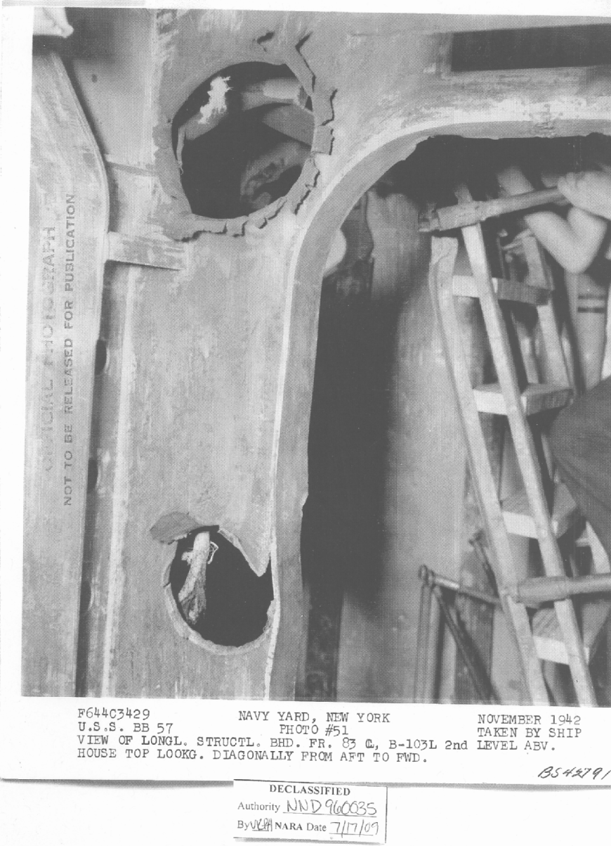
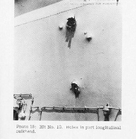
There are no inconsistencies with BuShips' estimate of an 8-inch AP projectile. At high velocity, the rather blunt end of this kind of shell (flat if the cap head is gone) would shear out very thin plating more like a paper punch than a wedge, keeping the hole narrow with only some minimal widening around the hole as the plate bent back in a ring of truncated petals around the hole (the center area of the plate under the nose that usually forms the upper end of the petals in a pointed-nose impact is sheared off as a disk/plug; round if at right angles, oval otherwise). A 5-inch hole for the cap head sounds about right, though it cannot penetrate much due to its light weight – perhaps an inch of steel, but that would stop it. The timing of this hit is unknown.
25. An estimated 5 or 8-inch projectile detonated upon contact with "N" strake of the shell just aft of frame 83 between the second and third deck levels. A hole about 3 by 2 feet was blown in the shell and torpedo bulkhead No. 2 was holed in numerous places by fragments. A tear in the shell plating extended forward to about frame 81-1/2. The rivets in the "N" strake were loose or missing between frames 82-1/2 and 84-1/2. Transverse bulkhead 83 was ruptured and distorted between the shell and torpedo bulkhead No. 2 from the second deck to the third deck. As a result of this hit tanks B-23-F, B-31-F, and B-39-F were flooded.
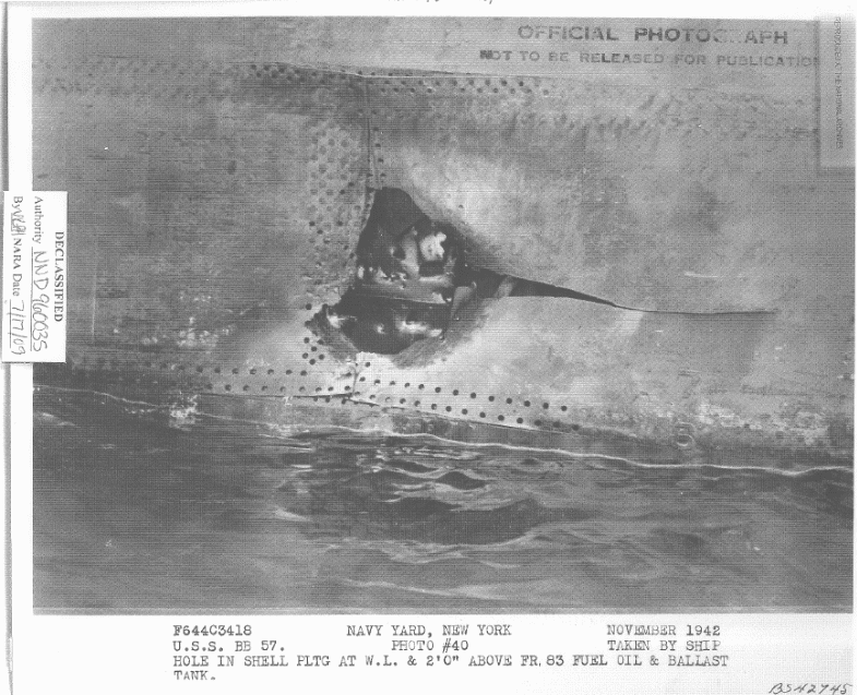
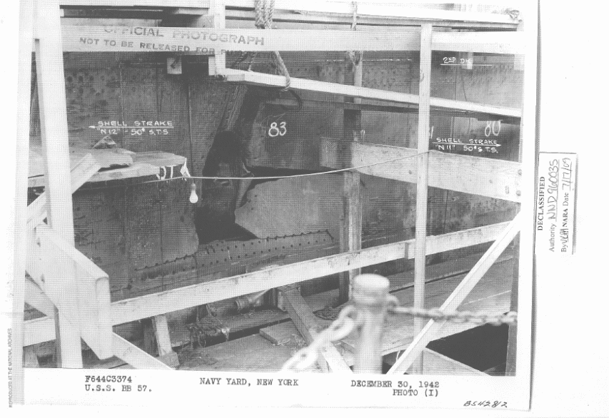
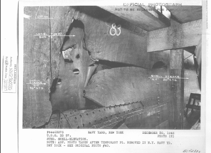
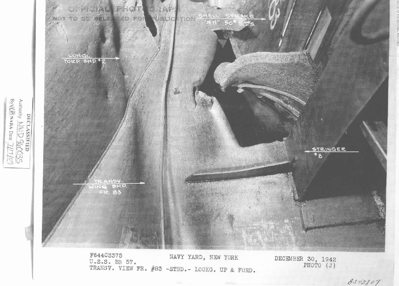
The STS plate at this point was 1.25 inches thick. The long tear in the plate to the right implies that the projectile hit at a quite high velocity and was coming from the right at a rather high angle of obliquity (about 45 degrees or so from the normal). The detonation blast split the plate, possibly due to a pre-existing lamination or other weakness (the crack is very straight and probably is parallel to the rolling direction used when the plate was manufactured). There are few deep pits in the plate around the big hole, although there are no other holes other than those made by torn-out rivets and bolts. The hit was up against a vertical seam between two of the STS plates where the plates are reinforced by doubling plates and straps and braced from behind by girders, using rather a lot of rivets and bolts. A number of large holes, tears and folds were made in the thin bulkhead representing the upward continuation of the first inboard anti-torpedo bulkhead in front of the armor belt, most probably by chunks of the 1.25-inch hull armor punched out by the projectile impact.
The shell exploding on impact indicates a nose-fuzed projectile. Using the same figures for a typical World War II HE shell as established for Hit 2; an 8-inch HE projectile was calculated as being able to produce a caliber-size hole in a 2.14 inch STS plate. For the thinner 1.25 inch plate found here, we can use Equation 2 to derive the hole size:
Hole Diameter = 8 x (2.14 / 1.25) = 13.7 inches
This is significantly smaller than the documented damage.
Using the same figures as established in Hit 2; for a non-Japanese World War II HE projectile, a caliber-size hole would be produced in a 3.86-inch thick STS plate. For the thinner 1.25 inch plate found here, we can use Equation 2 to calculate the hole size as follows:
Hole Diameter (for an HE shell) = 14 x (3.86 / 1.25) = 43.23 inches
As noted in the Hit 2 analysis, the smaller explosive filler in the 14-inch Type 0 HE projectile means that we should treat it as a SAP projectile:
Hole Diameter (for a SAP shell) = 43.23 x 0.864 = 37.35 inches
This is extremely close to the 3 foot hole documented in South Dakota's damage report. Thus, the best estimate for this damage is that it was made by a 14-inch Type 0 HE shell.
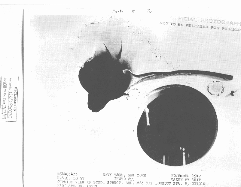
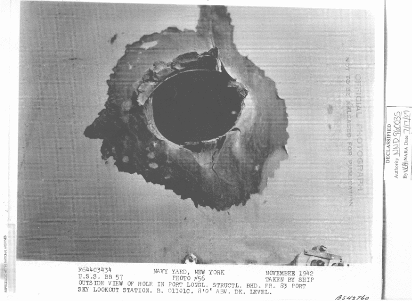
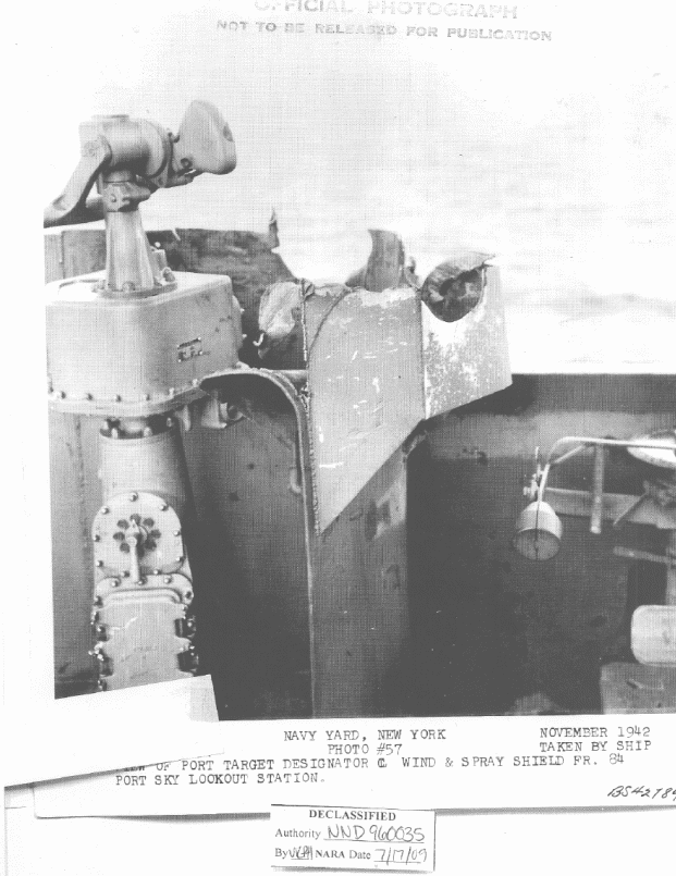
26. Another projectile, probably 8-inch AP, hit frame 83-1/2 about 8 feet above the deck of air defense forward. The projectile passed through two 60-pound STS bulkheads and shattered the top of the port spray shield at about frame 84 without detonating. Two 3-inch fragment holes were blown in the director tube.
[From "Chronological Log of the Battle" section of Action Report]
0055 Director 1 unable to train forward of 040 degrees relative, probably shell hits.
011 Level
Sky Control – 10" shell hole through 1¼" STS bulkhead frame 83 starboard.
10" hole through 1¼" STS bulkhead frame 83½ port.
12" battle cover and port frame broken at frame 83 starboard.
All insulation blown out.
2-3" shrapnel holes through protection casing center column of forward main battery director.
3/8" STS splinter shield around port target indicator is demolished.
Three swivel seats and brackets demolished. 41
GUNNERY DAMAGE
Main Battery
Director 1.
Electrical cables cut to the following:-
Pointers firing key
Salvo light
Battle order indicator
Range transmitter
Ships course input to director
Train designation transmission
Bearing on light
2JD8 telephone, selector switch – spot one
Radar inoperative, screen damage, frame cracked, transmission unit shot away.
Secondary Battery
Sky Forward (air defense station)
This station received three direct hits, two 8" and one 6", none exploded.
Damage follows:-
JY selector switch inoperative.
20MC and 21MC speakers destroyed.
Five telephone cables out to director 1.
Director tube pierced cutting 23 cables.
Battle ports carried away.
Electric heater destroyed.
Port target designator damaged.
5JP selector switch damaged.
Numerous cables cut, and lookout seat damaged. 35
The key to determining which projectile caused this damage is the time that director one was first documented as being unable to train due to shell hits, which was at 0055. At this point in the battle, the Japanese reports show that only the light cruisers were firing on South Dakota and that this damage occurred some seven minutes before the heavy cruisers opened fire. This means that this hit cannot have been from an 8-inch projectile. Turning then to look at the 5.5-inch Common projectiles fired by the light cruisers; normally the Type 13, Mark 1, Mod 1 base fuze used in the 5.5-inch Common would detonate these shells approximately 0.003 seconds after the initial impact (there is always a slight delay before ignition even with an instantaneous fuze due to the inertia of moving parts). However, the US Naval Technical Mission reported that this fuze gave many blinds, so this hit could have been made by a dud passing through the superstructure. 9 The shell trajectory matches the position of the light cruisers during this timeframe as the heavy cruisers are well ahead of South Dakota and are in the process of turning around between 0052 and 0055 (see Figure 69). Takao will be the first heavy cruiser to open fire at 0102, long after this damage is documented to have occurred. 42 Therefore, the best estimate for this damage is that it is from a dud 5.5-inch base-fuzed projectile fired by one of the light cruisers.
27. Three hits estimated to have been 8-inch AP were made in the starboard bulkhead between frames 83 and 85 from 5 to 8 feet above the third level above the house top. These projectiles ripped through the transverse passage and the radar plot then out the port side, demolishing the top of the port spray shield between frames 83 and 86. Bulkhead 84 had a 30 by 60-inch hole. The port longitudinal structural bulkhead was perforated by at least five holes about two feet in diameter. All equipment and instruments in radar plot were demolished and a fire was started. In spite of the extensive damage there was little evidence that these projectiles detonated.
[From "Chronological Log of the Battle" section of Action Report]
0057 ... Enemy hits in vicinity of radar plot. Shell through radar plot immediately after this killed Ensign Canfield. Steam line ruptured just outside of radar plot by 6-inch shell which penetrated into radar plot on port side and demolished it. Another shell very near same place immediately followed.
08 Level
Watertight door and door frame 08-82-1 blown out.
1-10" and 1-12" shell hole through starboard longitudinal bulkhead at frame 83. (25 pound STS plate)
3 bulkhead stiffeners and supporting beams severed, twisted. Frames 83-84 starboard.
1- 36", 1-8", and 1-6" shell and shrapnel holes through longitudinal centerline bulkhead.
1-4" x 6" shrapnel hole in deck plating, frame 84 centerline.
1-30" x 60" hole in transverse structural bulkhead 84.
4 bulkhead stiffeners and supporting beams on transverse bulkhead severed.
All sheathing and insulation blown out.
Forward starboard yardarm and supporting brace cut.
1-18" hole through port bulkhead [Author's Note – Actually starboard bulkhead] at frame 84.
4" hole through watertight door at frame 84 starboard.
1-8" hole in structural bulkhead starboard 5' above deck level radar plot.
1 section of structural bulkhead 8' by 10' blown out between frames 85-87 port, radar plot.
All sheathing overhead and bulkheads torn by shrapnel, radar plot.
Exhaust vent duct demolished radar plot.
Access door to passage B-103L and radar plot missing.
Starboard access ladder from 8th to 9th level demolished.
Entire longitudinal section of wind and spray shield and stiffeners between frames 84-87 demolished.
Catwalk around secondary Conn., 2-4" shrapnel holes through deck plating, centerline.
19' protective casing around radio direction finder installation under overhang of catwalk completely demolished.
3-3" shrapnel holes through after section wind and spray shield starboard.
2-3" shrapnel holes through stem.
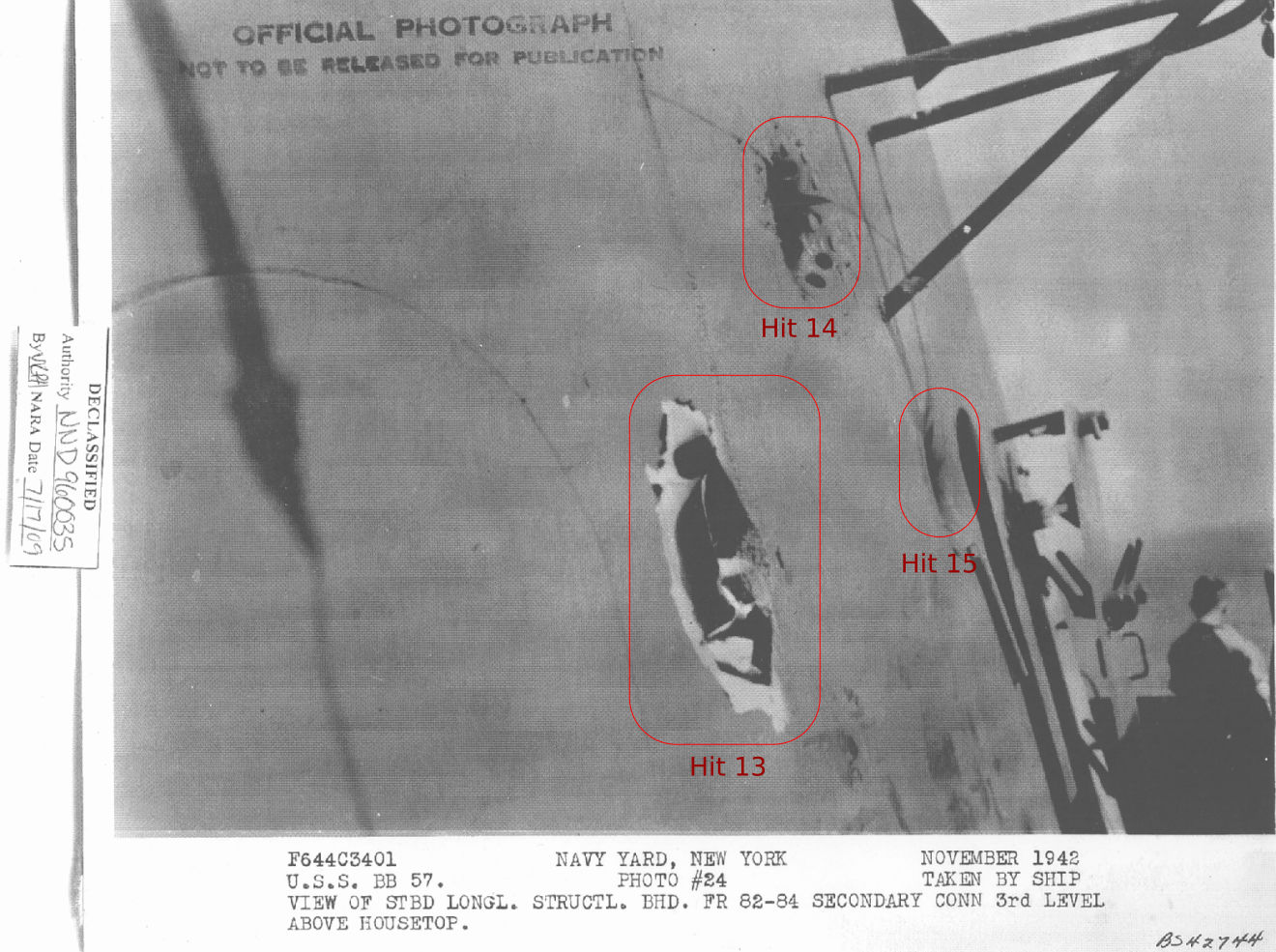
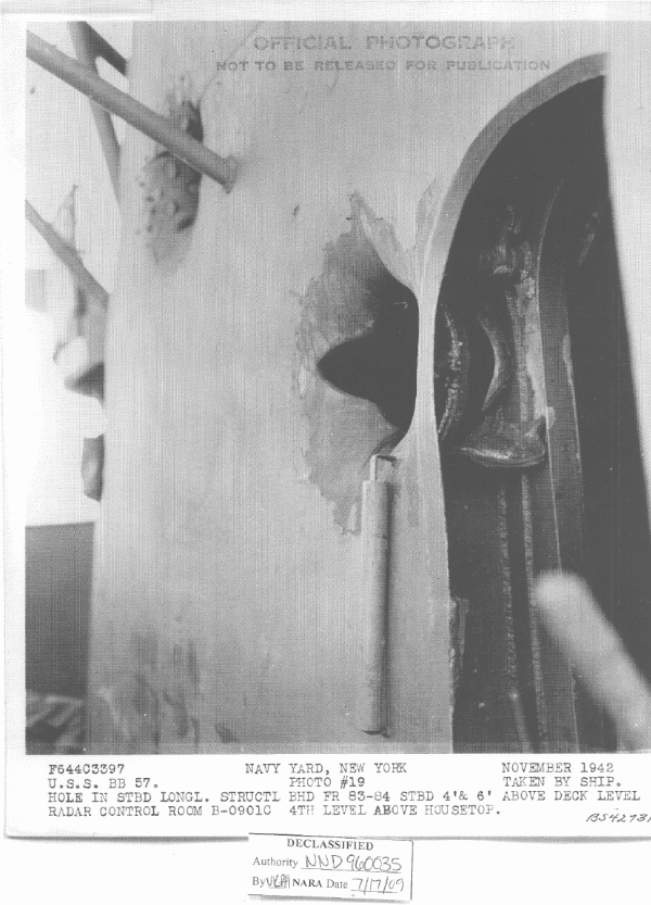
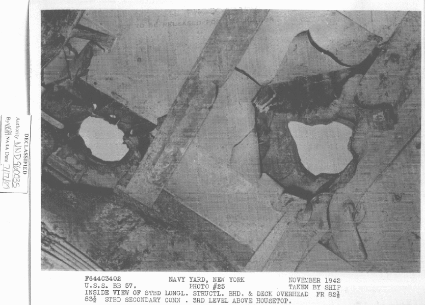
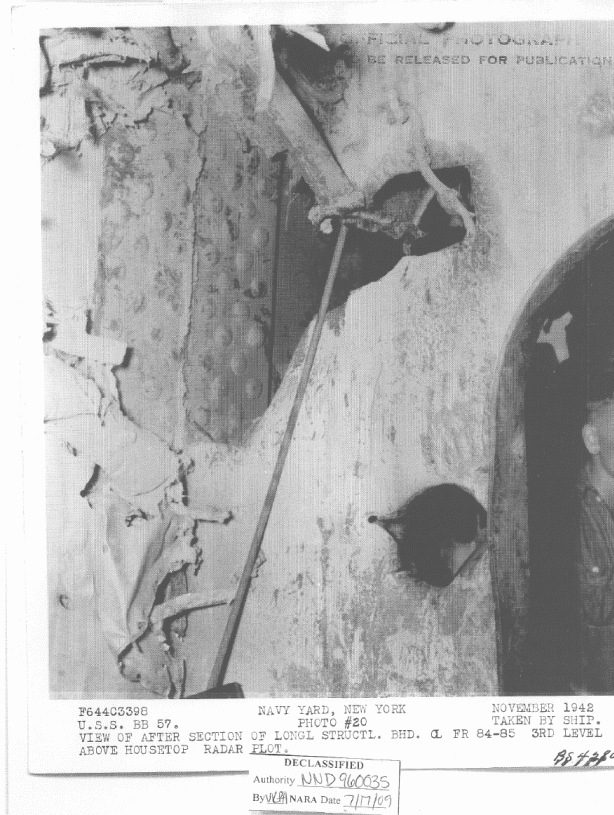
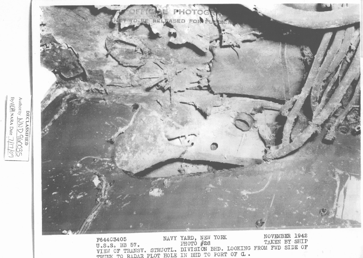
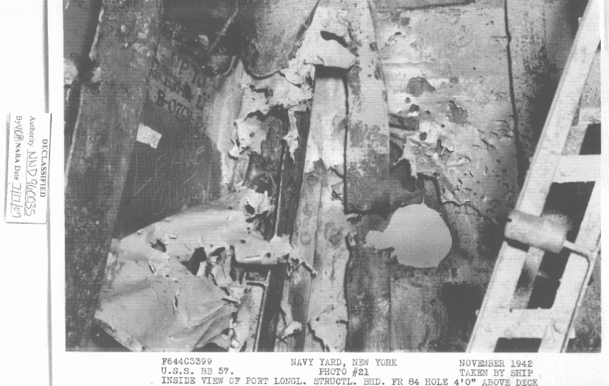
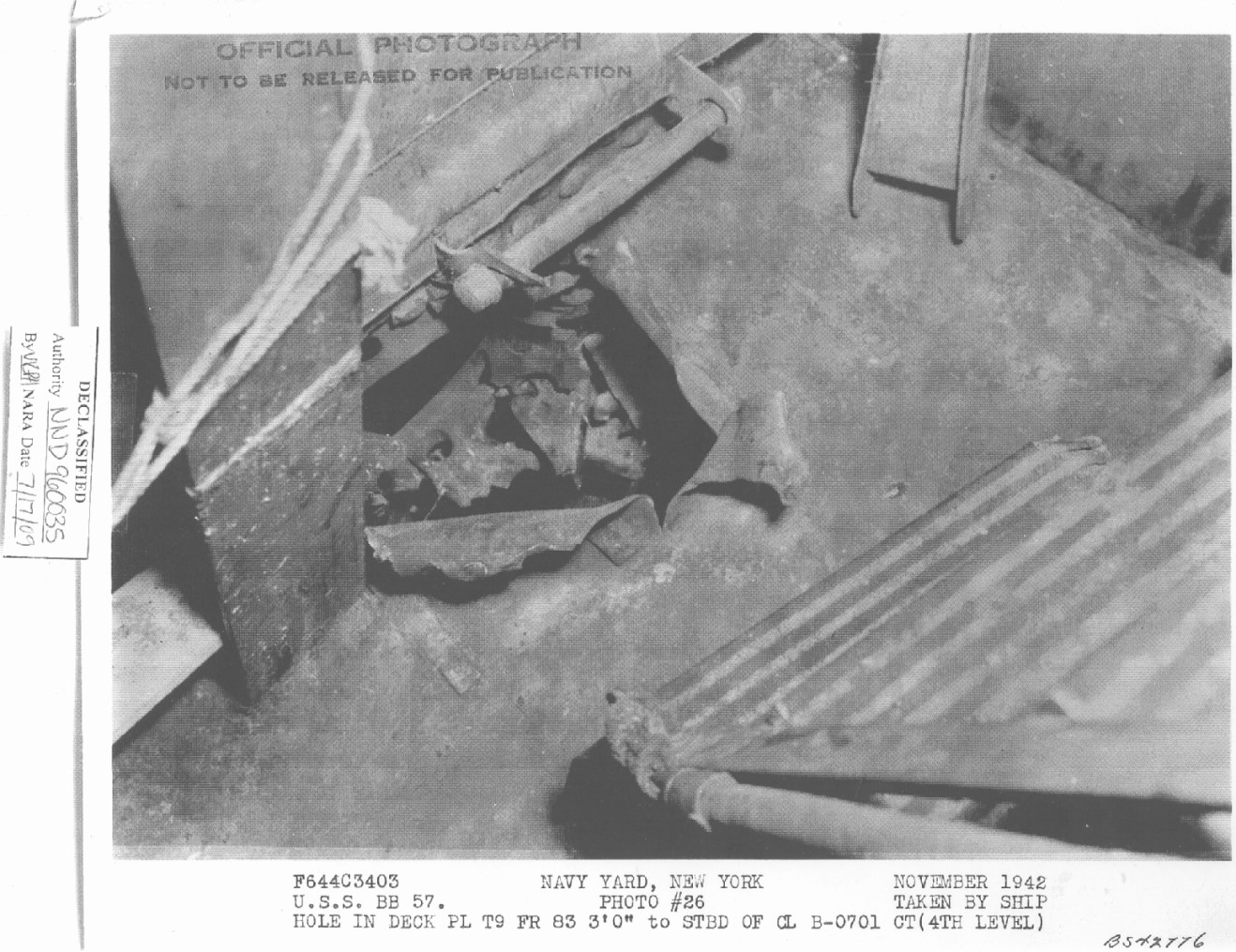
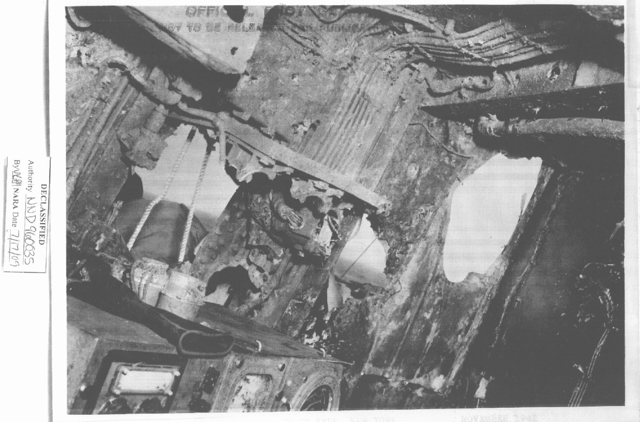
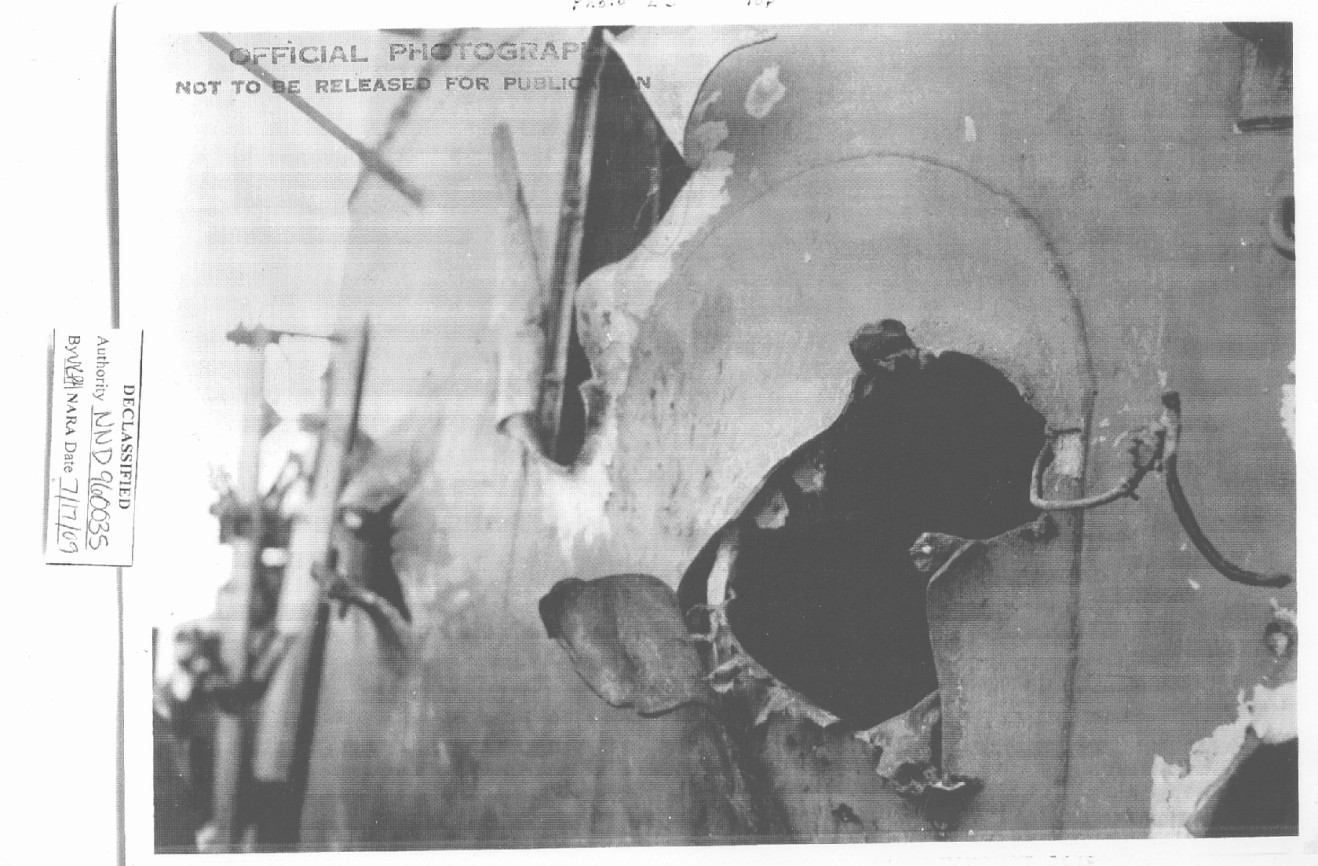
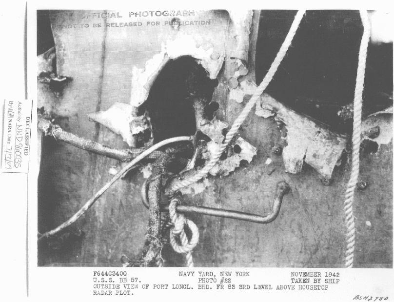
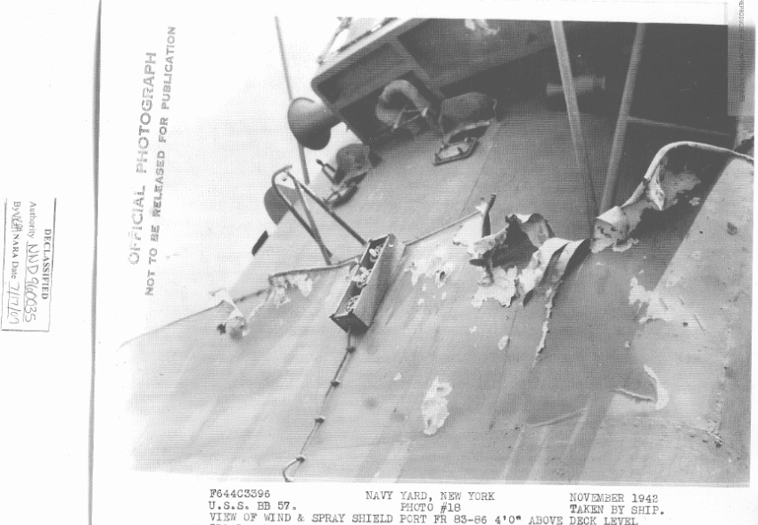
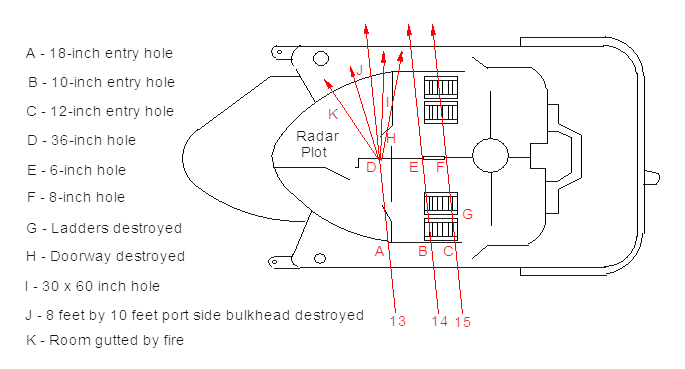
The first inconsistency about BuShip's estimate of three 8-inch shells is that these hits are recorded long before the heavy cruisers opened fire. South Dakota entered this damage into her logs at 0057, however the damage actually occurred a few minutes earlier at 0052-53, which is the time that Kirishima first opened fire. At this same time, South Dakota recorded her first sighting of three ships at 11,000 yards and logged that she was taking hits to her foremast. 37 Between 0052 and 0054, South Dakota veered south and this change in course was documented by USS Washington as having occurred at 0054. 48 This places South Dakota as being broadside to Kirishima with her stern towards the light cruisers. The Takao will not open fire until 0102 and Atago not until 0103, so the estimate of 8-inch shells becomes impossible. In addition, the damage seen is not consistent with AP ammunition. These hits were eye-witnessed by Admiral Kondo and LCDR Ikeda as having occurred when Kirishima opened fire at 0052. Finally, what is entered into South Dakota's logs also matches Ikeda's description of how Kirishima opened fire: Ikeda said that his secondary battery fired first, quickly followed by the main battery. He saw two hits strike the target ship in the foremast from this salvo, which closely matches the time recorded in South Dakota's log. 49
In looking at the entry holes shown in Figure 42, the hole created by Hit 13 is visibly larger than the other two and is 18 inches in diameter. Referencing the sketch in Figure 53, this impact occurred at point (A) and this shell then blew a 36-inch hole in the centerline bulkhead (D) and began to break up. The door leading to radar plot (H) and the passageway were blown out. Shell sections and fragments then hit the transverse bulkhead (I) at Frame 84, blowing a 30 by 60 inch hole. This projectile continued to disintegrate, breaking up completely and exiting through the port side in an area of 8 by 10 feet (J) and creating at least five holes in this area that are over 24 inches in diameter. The photographs for this damage show circular but also irregular shaped exit holes, a characteristic that indicates that the shell broke apart. Although this shell did not explode, it did start a large fire which gutted this compartment. In addition, the surrounding catwalk, wind and spray shields and the radio direction finder were all showered with shrapnel, causing many small holes.
Shrapnel also blew out the deck plating of the 09 level above the radar plot, creating one 12 x 18 inch hole in the deck plating at Frame 84 on the 09 level and an 18 x 36 inch hole through the deck plating at Frame 84 of the port radar transmitter room. The access ladders going between the 09 and 010 levels were also demolished.
This damage is consistent with two 6-inch shells and one 14-inch Type 3 incendiary shell. The nose fuze on the 14-inch Type 3 and the long fuze rod that ran down the middle of the shell to its base would have snapped under impact, preventing the detonation of the small explosive charge. As the shell ripped through bulkheads, the wood nose and thin sides of the shell would be torn away and the shell would disintegrate, throwing its shrapnel in every direction like a shot gun blast, taking out the doorways and bulkheads in its path. Some of the 3-inch long incendiary tubes ignited, probably low-order because the shell did not detonate properly, which started the fire within the compartment. From Admiral Kondo's point of view, it looked as if the shell had blown off the top of South Dakota's main mast. The display of the incendiary tubes igniting from this hit must have appeared to the eyewitnesses on the other ships like a giant firework. Two nights previously, two 14-inch Type 3 shells had struck the heavy cruiser USS San Francisco and these shells also broke apart and started low-order fires in the areas they went through. In her case, the shells passed through the lower superstructure and upper hull and hit the forward barbette such that most of the incendiary tubes were trapped inside the ship, causing much larger fires. In South Dakota's case, it appears that much of the contents of the Type 3 shell passed clean through the ship and went overboard, leaving relatively few tubes to ignite or be recognizable during the clean-up afterwards.
This damage confirms what is documented in the Japanese action reports; that Kirishima was not only the first ship of the Bombardment Group to open fire, but that she also hit South Dakota with her first salvo.
28. Three hits were made on the starboard bulkhead between frames 83 and 85 about 3 feet above the second superstructure deck. From the size of the entry holes, it is estimated that these were one 8-inch and two 6-inch AP projectiles. The 8-inch projectile ripped through five structural bulkheads and was stopped by the shield of 5-inch mount No. 2, knocking off the rear door of this mount without detonating. When the projectile was discovered after the battle, it was quickly thrown overboard. In staterooms 0202, 0203, 0205, the unassigned space under the starboard signal locker, and B-103-L through which the projectiles passed, furniture, ventilation ducts, metal joiner doors and aluminum division bulkheads were demolished. Less extensive shock and fragment damage was sustained in staterooms 0204, 0206, 0207, and B-0201-L. One fragment pierced the starboard signal flag locker and started a minor fire.
[From "Chronological Log of the Battle" section of Action Report]
0104More hits felt. Secondary battery is still firing.
No communication with sky control.
Shell hit, glancing off mount 5, through signal storeroom, across superstructure, and into after end of mount 4. Shell did not explode, later found on deck, 8-inch disposed of by throwing overboard.
WRSR 0205. Salvo of 3 projectiles (belived [sic] to be 6") entered longitudinal bulkhead at frame 84, approximately 3' above 2nd superstructure deck resulting in the following damage:
- Entire transverse aluminum divisional bulkhead between WRSR 0205 and locker used for stowage of forms completely blown out.
- Inboard longitudinal structural bulkhead has 30" diameter hole approximately 3' above deck level.
- Secretary desk completely demolished.
- Confidential safe demolished.
- Wash basin and cabinet demolished.
- Overhead supporting deck beam frame 82 torn open 4" x 6".
- Ventilation duct demolished.
- Hot and cold water piping and drains completely demolished.
- Metal joiner door to passage demolished.
- Metal enclosure and binding strips of berth torn and distorted by shrapnel.
- 10" hole approximately 32" above deck plate in outboard longitudinal structural bulkhead.
- Unassigned compartment under starboard signal flag bag used for stowage of XO office forms.
- All shelving completely demolished by shrapnel.
- Bottom of starboard signal bag blown open at seam approximately 4' x 2'.
- 3 outboard bulkhead stiffeners on after transverse bulkhead pierced by shell fragments, holes approximately 3" in diameter.
- Welded seams torn.
- Outboard longitudinal bulkhead pierced by shell fragments approximately 8" in diameter, frame 85, 4' above deck level.
- 30" hole in inboard structural bulkhead.
- 2" drainage line on inboard and outboard ends of signal bag torn out.
- Deck plating dished over 3' square area, 8' inboard of longitudinal structural bulkhead.
- Non-watertight door pierced by shrapnel and is unserviceable.
- 6" aluminum ventilation duct demolished.
- Ventilation terminal of supply ventilation system demolished.
WRSR 0207.
- Frame 87½ battle port 2" hole.
- Metal Joiner door to passage distorted.
- Door frame pierced by shrapnel.
- After transverse structural bulkhead pierced by fragments ranging from ¾" to 3" in diameter.
Passage B-0201L.
- Door frame of metal joiner door access to B-103L pierced by fragments.
- Drain line for upper level stateroom pierced by 3 fragments approximately 5' above deck level. Exhaust ventilation system duct torn and blown open.
- 2" fresh water supply lines to 2nd and 3rd superstructure deck staterooms severed 2' above deck level.
WRSR 0204.
- Metal joiner door and frame blown out and distorted. Inboard longitudinal panel bulkhead blown out.
WRSR0206.
- Inboard longitudinal panel bulkhead demolished.
- Metal joiner door and frame broken.
B-103L.
- 2nd superstructure deck. 25" by 8" T bars bulkhead stiffeners on starboard longitudinal structural bulkhead at frame 83 severed 2' above deck level.
- Access ladder and fittings to 3rd superstructure deck demolished.
- Hot water tank (supply to system on 2nd superstructure deck) demolished.
- Topping lift and big falls for starboard boat crane damaged.
- Three 4" fuel hoses damaged. #1 MWB 52 damaged. (26 small shrapnel holes).
- Electrical booster pump and all connections completely demolished.
- Steam line supply and drain to hot water tank completely demolished.
- Longitudinal centerline structural bulkhead demolished at frame 84.
- Ventilation supply and exhaust lines severed and demolished at frame 82½ port.
- 1 ¼" compressed air line severed at frame 82.
- First aid box and supports demolished.
- Intake and exhaust ventilation ducts demolished, starboard.
- Port longitudinal structural 30 pound bulkhead and stiffeners completely demolished.
- Seams to fresh water gravity tanks leaking.
- Stanchions on access ladder cut and broken.
- Combing of access hatch to first superstructure deck bent and distorted.
WRSR 0202
- Metal joiner door and frame demolished.
- Large ship's confidential safe demolished.
- Secretarial desk demolished. Built in metal berth demolished. Wardrobe locker demolished. Chiffonier locker demolished. Sheathing and insulation torn out over entire area. Wash basin and connections torn from fastenings.
- Shaving cabinet broken. 53
Secondary Battery Group #2
... Mount #2 was struck by 6.1" projectile which had passed through superstructure from starboard side. This projectile did not explode. The projectile struck door to left hit case chute, then up rear of shield. The rear armor plate is pushed in and broken loose from top, sides, and bottom plates. The angle beam is cut. Oil reservoir tank of left shell hoist punctured. 39
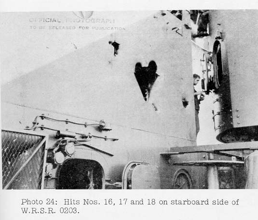
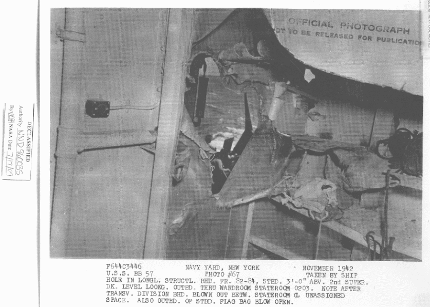
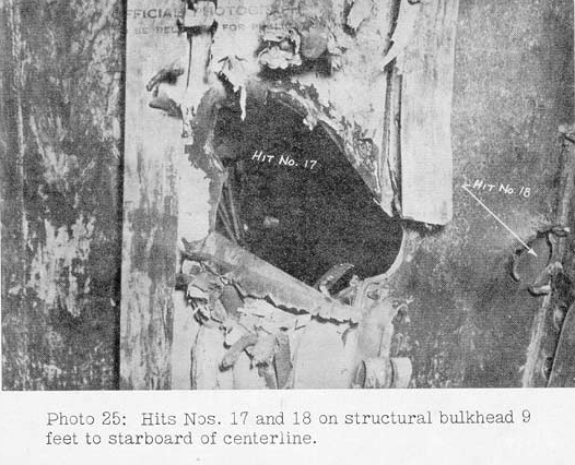
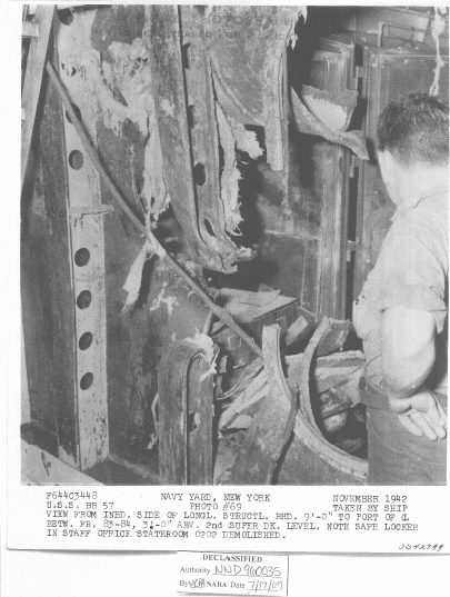
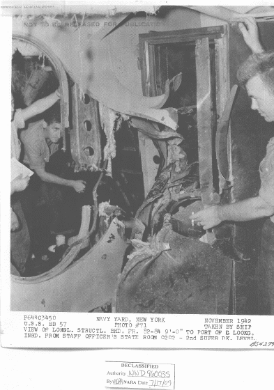
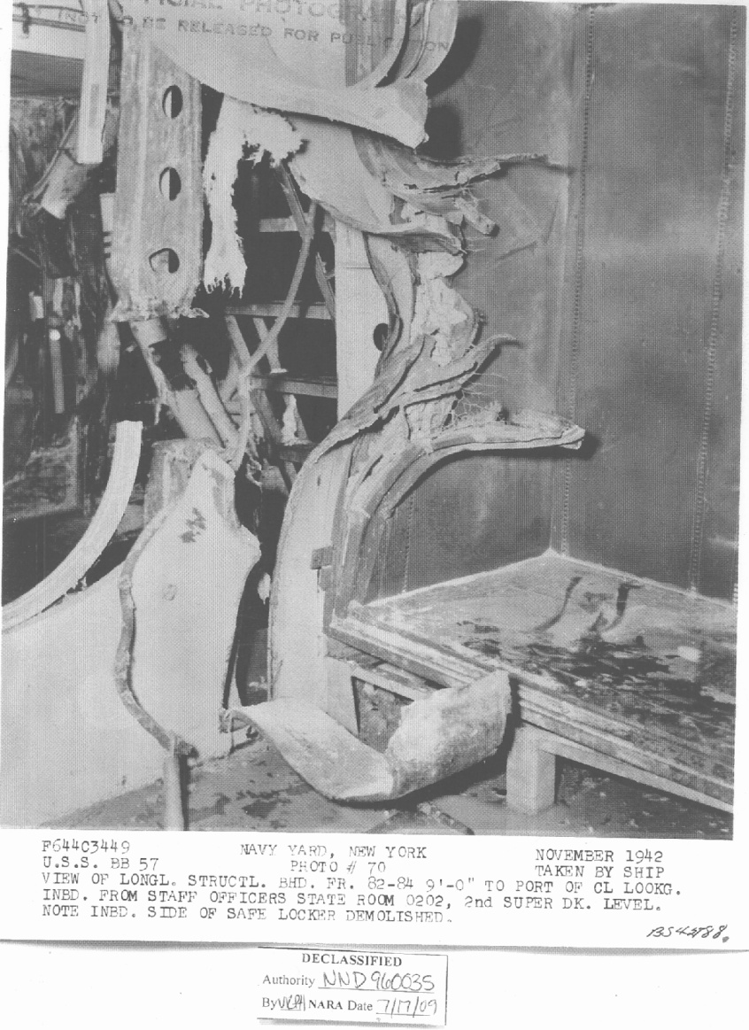
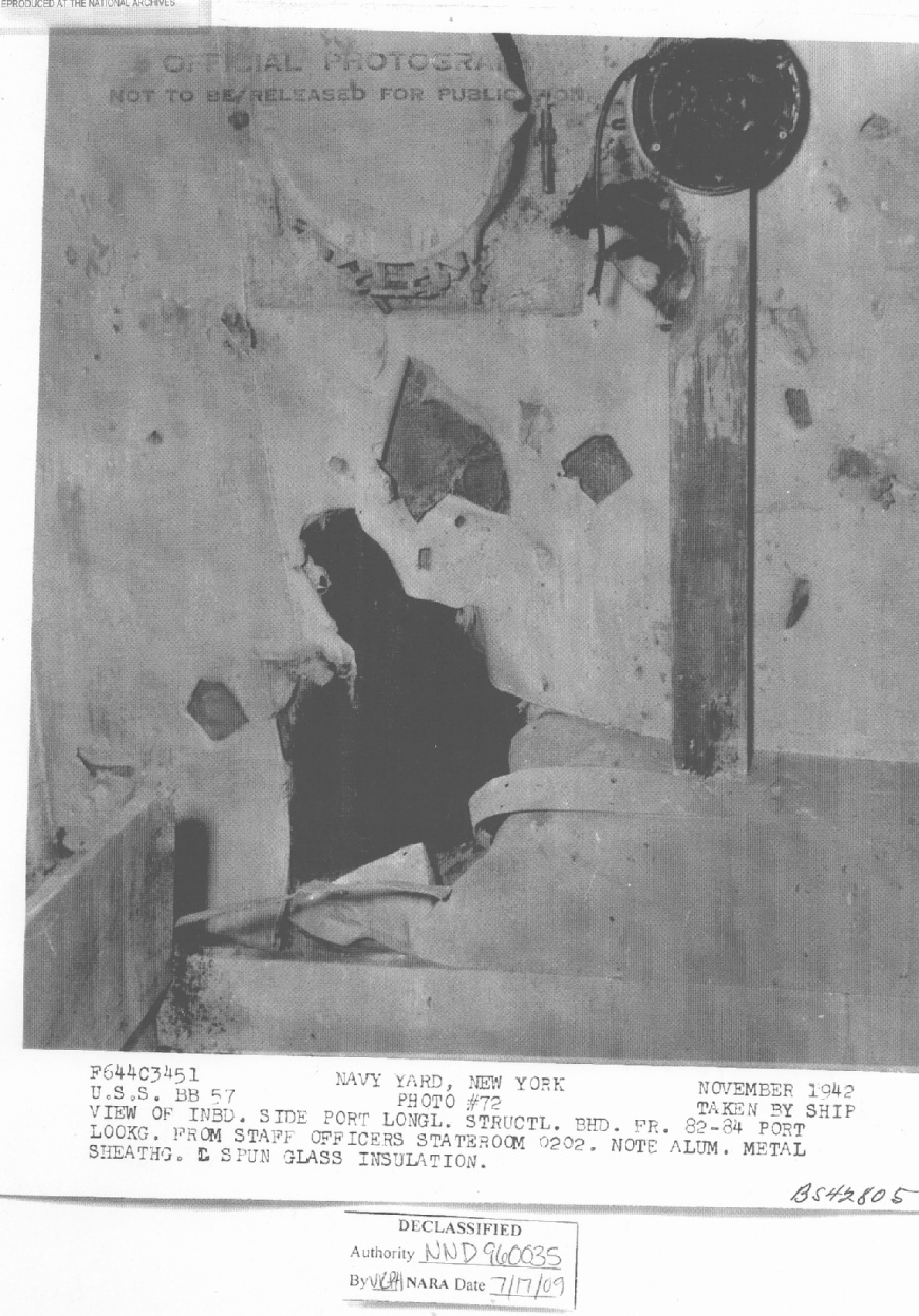
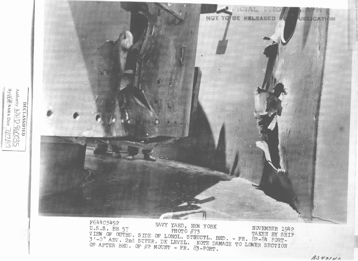
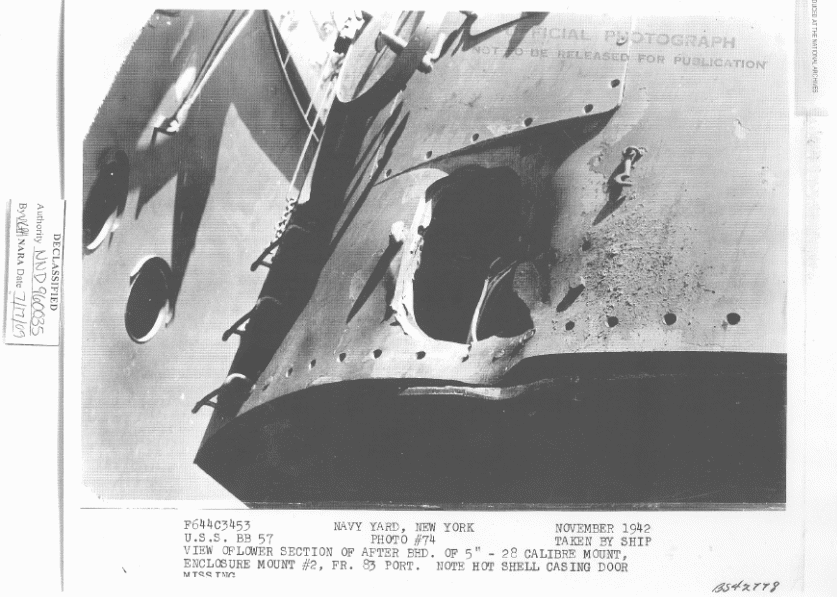
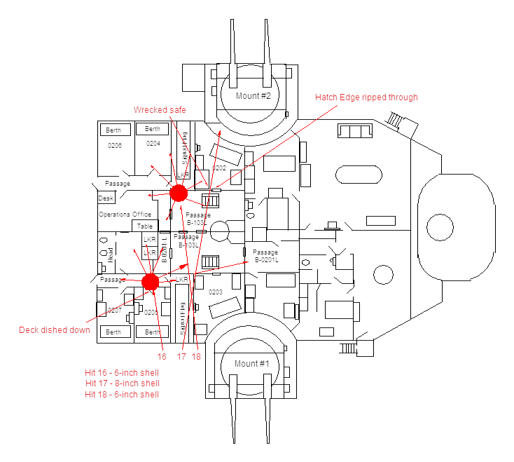
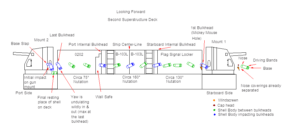
The documentation on these three hits is very inconsistent, but in the end the estimate of two 6-inch and one 8-inch projectiles appears to be correct. First, the photograph labeling the entry hits at WRSR 0203 ( Figure 54) is misleading in that two of the shells actually entered WRSR 0205 and into the starboard Signal Flag Locker room and only Hit 18 actually entered via WRSR 0203. Secondly, the shells were not part of a single salvo as the shell trajectories of the two 6-inch shells (Hits 16 and 18) are from forward moving aft while the 8-inch shell (Hit 17) must have came from aft moving forward or else it would have completely missed mount two. This can be seen in Figure 56 where Hit 17 came through a bulkhead moving right to left while Hit 18 was moving left to right. The two 6-inch shells appear to have detonated, causing blast and fragment damage to the staterooms. The relatively small 10-inch entry holes seen for these hits appear to be more consistent with 6-inch shells.
Hit 16 appears to have detonated on the inboard side of compartment WRSR 0205 as the deck plating was dished down over a 3 foot square area, 8 feet inboard of longitudinal structural bulkhead. The entire transverse aluminum divisional bulkhead between WRSR 0205 and the locker used for stowage of forms was completely blown out. This inboard longitudinal structural bulkhead also had a 30-inch diameter hole knocked in it approximately 3 feet above deck level. Plate 1 of BuShip's original report (shown as Figure 123 in this essay) has a notation that implies that none of these three projectiles detonated, but South Dakota's action report makes it clear that the two 6-inch projectiles did indeed detonate within the superstructure.
The holes in the bulkheads for Hit 17 appear too large for a 6-inch shell and, contrary to South Dakota's action report, there were no guns present at this battle that fired a 6.1-inch shell. The only 6.1-inch guns in the vicinity were part of the battleship Yamato's secondary battery and she was anchored miles away at Truk.
Based on the photographs, it appears that the entry hole caused by the shell passing through to hit mount 2 is significantly larger than 10 inches. The first clue to its identity is the shape of the entry hole shown in Figure 54 and Figure 55. Examining these two photographs show that Hit 17 made a "V" shaped entry hole along with two circular holes at the top giving it "Mickey Mouse" ears. This is an odd shape for an entry hole, as can be seen comparing it with the round holes made by Hit 16 and Hit 18.
What could have caused this oddly-shaped entry hole? A possibility is that the shell components separated before reaching the bulkhead. If we think of an 8-inch AP projectile as having a windscreen, a cap head and a shell body, then the bottom of the "V" may have been caused by the windscreen (point down) with the left and smaller circular entry hole being from the cap head and the larger circular hole on the right being caused by the shell body.
To have broken up like this, the projectile must have already hit something hard enough to dislodge its nose coverings prior to impacting this exterior bulkhead. This could only have been the water short of the ship, which would have also slowed it down considerably in the process. So, this hit could have struck at too shallow an angle to "bite" into the water and instead it ricocheted up to hit the superstructure, shedding its nose-coverings as it went. 54
After hitting the water, the windscreen and cap head of the 8-inch AP shell were knocked off and the projectile slowed down considerably before ricocheting upward at a very shallow angle, slamming into the starboard bulkhead to form the Mickey Mouse Hole. In the water ricochet process, the nose acquired a significant "yaw" angle, which is the tilt of the nose away from the direction of motion of the projectile caused by the water impact pushing on the upper end of the projectile with a different force than on the base end. The projectile thus began to move forward like a surfboard, cocked off at an angle to the direction it was moving, in this case about 20-30 degrees, as shown by the oval hole in Figure 56. Since the projectile was still spinning at a high rate, however, this yaw started to "nutate" 55 as soon as it left the water so that the nose punched through the superstructure bulkheads with the yaw angle pointed in progressively different directions, as shown in Figure 64.
While the direction of the yaw changed due to the nutation, the amount of yaw stayed more-or-less at the same 20-30 degrees it had when it initially made part of the Mickey Mouse Hole over most of its path through the superstructure, as shown in Figure 56 (the picture here is from the exit side of the hole, so it is a mirror image of the actual direction that the yaw was pointing when it punched through the bulkhead toward the camera).
Figure 66 shows how the nutation angles are used in this document. Zero degrees nutation is directly on top. Positive degree nutation angles are in a clockwise direction while negative degree nutation angles are in a counter-clockwise direction from the zero point. Negative angles may also be referred to as a Positive angle by measuring in the clockwise direction. For example: -124 degrees is equivalent to a Positive Angle of +236 degrees. The letters shown in Figure 66 refer to the nutation angles as the shell body impacted the bulkheads as it traveled through the superstructure as labeled in Figure 65.
For Hit 17, when this shell entered the exterior starboard bulkhead of the Flag Signal Locker, the shell nose was at a nutation angle of +15 degrees (Refer to Figure 65 Point A). The shell was nutating in a counter-clockwise direction.
The shell then ripped through a thin transverse bulkhead to exit the Flag Signal Locker (Refer to Figure 65 Point B) and entered Compartment 203 at a highly oblique angle, but very close to its inboard end, so the bulkhead has little deflection effect as the projectile tears through it. Since the projectile body has a flat nose and such a small yaw, the forces generated are still very close to directly down the centerline of the shell, so any added yawing effect (increasing or decreasing) by penetrating this transverse bulkhead was minimal.
The projectile then hit the longitude inboard bulkhead of compartment 203 (Refer to Figure 65 Point C). The nutation angle at this point had progressed to -124 degrees based upon Figure 56. The yaw angle remained at about 20-30 degrees. The distance from the exterior bulkhead to this inboard bulkhead is 16.0 feet and taking into account that the trajectory is on an approximate 10 degree composite angle, this changes the actual distance traveled to 16.24 feet [16 feet x 1/cos (10 degrees) = 16 feet x 1.015 = 16.24 feet]. There has been a total of 139 degrees change in nutation (-15 degrees + -124 degrees = -139 degrees), so -139 degrees/16.24 feet = -8.5 degree change per foot of travel.
The next bulkhead is the centerline bulkhead of the ship in Compartment B103L (Refer to Figure 65 Point D). This bulkhead is 9.0 feet from the inboard bulkhead of compartment 203. The 10 degree angle for the shell trajectory adjusts the actual distance traveled to 9.14 feet [9 feet x 1/cos (10) = 9 feet x 1.015 = 9.14 feet]. Maintaining the same nutation rate of -8.5 degrees per foot, an additional -78 degrees (9.14 feet x -8.5 degrees = -78 degrees) will result with the shell impacting this bulkhead with a nutation angle of +158 degrees (-124 degrees + -78 degrees = -202 degrees = Equivalent Positive Angle +158 degrees) with the yaw remaining constant.
The next bulkhead is the inboard side of compartment 202 (Refer to Figure 65 Point E). This bulkhead is also 9.0 feet away from the ship's centerline. The distance and nutation rate remains the same as for the previous bulkhead, so the projectile's nose impacted this bulkhead with a nutation of +80 degrees (+158 degrees + -78 degrees = +80 degrees).
However, there was a wall safe on the other side of this bulkhead inside compartment 202. The now-nearly-horizontal projectile's lower body broad-sided the 2-inch-thick left side of the large double-door safe, as shown in Figure 59 (also shown in Figure 57 and Figure 58, but not as clearly). 56 That violent middle-body impact with the safe caused the yaw angle to begin swinging wildly in and out, to angles well above the original 20-30 degrees, perhaps up to 60 degrees away from directly along the flight path, and the nutation rate also changed to approximately -5.3 degrees per foot, although the shell would still be nutating in the counter-clockwise direction. This is to be expected since the larger yaw angle acts like a rapidly-spinning ice-skater spreading her arms out and slowing her spin rate down due to conservation of angular momentum.
The distance from the wall safe to the curved exterior bulkhead of compartment 202 (Refer to Figure 65 Point F), is 12.35 feet. With the new nutation rate, the projectile nutated an additional -65 degrees (12.35 feet x -5.3 degrees = -65 degrees), so that the shell on impact with the port exterior bulkhead had a nutation of +15 degrees (+80 degrees + -65 degrees = +15 degrees). As shown in Figure 61, the projectile then "belly-flopped" through this bulkhead and made that long slot that was almost identical, though longer, to the initial slot (mostly masked by the long windscreen hole) it made on the starboard bulkhead. The projectile nose had thus spiraled through one complete circle during its passage through the superstructure (see Figure 64).
As shown in Figure 61 and Figure 62, the projectile kept that high yaw angle in the gap between the port bulkhead and the back of the 5-inch gun mount (Refer to Figure 65 Point G). The gap distance is 3.25 feet and, using the nutation rate of -5.3 degrees per foot; -5.3 degrees x 3.25 feet = -17 degrees change in nutation angle), the shell impacted the gun mount at a nutation angle of -2 degrees (+15 degrees + -17 degrees = -2 degrees), angled almost exactly vertical, nose up, at the point where its forward motion was finally stopped.
Referencing Figure 68, the nose hit the 5-inch mount at the lower-right-hand corner of the left-side-gun's shell casing ejection hatch (A) and punched a deep pit and hole, but did not completely penetrate. The tapered flat nose was jammed into that hole and could not move while the base continued forward, slamming vertically nose-up into the rear of the gun mount (90 degrees yaw angle and -2 degrees nutation angle), as noted by the curved dent in the lower edge of the rear armor and the gash in the edge of the armor floor plate below that (B). As the nose was jammed into the deep dent and hole, this rotation pulled out the armor just above the nose hole, since it is now shallower than the dent higher up on the right edge of the case-ejection hole. The projectile body hit the lower-edge armor sideways at a high nutation rate, as shown by the depth of the dent, and then rebounded outward, pivoting on the jammed nose (C). The nutation inertia was still in force, however, so the rotation of the lower projectile body toward the horizontal, reducing the 90 degrees yaw angle toward zero, was accompanied by the nutation of the projectile base to the left, counter-clockwise, just as before the armor impact, but now pivoting on the nose tip, not the shell center-of gravity about halfway down the shell length (D). This caused the base to move in a curve like a question mark without the bottom dot and end up slamming horizontally on the far left side of the case-ejection opening from the nose hole (90 degrees yaw angle and a 90 degrees nutation angle), as shown by the rectangular dent there (E). This cross-wise slam across the closed hatch covering the case-ejection opening rammed the hatch cover through the opening into the gun mount, tearing out the edge hinges and locking clamps and causing deep tears/dents all around the edge of the opening. In the process, the nose pulled out more of the armor trapping it, pulling up the raised torn area to the right and below the nose hole.
After this second horizontal base impact, the projectile no longer had any energy and the base fell downward, so the weight of the shell finally twisted the nose free of the hole in the mount. The projectile then fell to the deck, still spinning for a few minutes in a circle, but not moving very far (F). It was found right there by crewmen after the battle and thrown over the side.
This shell did not explode on impact with the safe or gun mount because it was moving so slowly (at the range of the gun which fired it, a shell with no yaw that was not slowed down considerably by the water impact would have easily punched entirely through that 5-inch mount); hit rather soft, thin (compared to the shell diameter, that is), and easily dented steel (the force on the fuze firing pin was reduced because it was spread over a longer time than a sharp penetrating-impact shock); and hit at such a high yaw angle that the firing pin was probably jammed sideways and could not move in the fuze, even with a stronger force than actually occurred (such fuzes are not designed for such yawed impacts). Hit 26 on Turret III barbette, as will be discussed later, shows a similar lack of fuze initiation. Both of these impacts had rotations along two planes; one along the direction of flight (the base moving forward to hit the same plate the nose had previously hit) and one at right angles to that direction rotating from a nose-down vertical yaw to a horizontal yaw parallel to the deck using a counter-clockwise one-quarter-circle turn with the projectile nose tip as the pivot point.
Hit 18 probably detonated on the inboard, port side and aft close to compartments WRSR 0204 and 0206. In WRSR 0204 the metal joiner door and frame were blown out and distorted and the inboard longitudinal panel bulkhead was blown out. In WRSR 0206, the inboard longitudinal panel bulkhead was demolished and the metal joiner door and frame broken. Fragments damaged the Operations office, B-0201L, and B-103L as well.
We believe that Hit 17 was from the 8-inch AP shell that was later found on deck and that the correct shell size was indeed 8-inches, even though South Dakota's logs confuse which gun mount was hit. The heavy cruisers opened fire late, at which time they were abreast and then aft of South Dakota during their firing passes. The shell trajectory and timing of the 8-inch shell matches the heavy cruisers position while the trajectories of the 6-inch shells match Kirishima's position (see Figure 69 57) at 0104 when this damage was listed as occurring in South Dakota's time logs. This also eliminates the possibility of the shell being a larger caliber one as at the time this hit was made Kirishima was still forward of South Dakota and not aft. For Hits 16 and 18, the best estimate is that they were base-fuzed 6-inch Type 4 Common projectiles, as these shells did not explode on impact with the outer bulkhead but were able to penetrate inside the ship before they detonated.
29. No. 3 36-inch searchlight received a direct hit estimated to have been an 8-inch projectile that passed through without detonating.
Searchlight 3 - pierced by projectile passing through lens, shutter and reflector.
The amount of damage to the search light was minimal. The shell did not detonate, indicating that it was not a nose-fuzed projectile. It also does not appear to have been an 8-inch AP projectile as the light windscreen of that shell would have ripped-off and flattened, causing much more damage than was the case (for example, Hit 6 from an 8-inch AP projectile created an 18-inch wide hole in a 0.25-inch thick STS plate and Hit 9 made a 17-inch hole). An 8-inch AP projectile would thus have created a hole approximately half of the diameter of the 36-inch searchlight. A smaller base-fuzed 5.5-inch Type 2 Common projectile or 6-inch Type 4 Common projectile would have nothing to come off and these are basically solid rounds. A hit by one of these projectiles would have gone right on through the searchlight, which is consistent with the damage as shown in Figure 70. Based upon examining this photograph; the hole is about 10 to 12 inches in diameter, which is consistent with the other 5.5-inch and 6-inch caliber hits. The timing of this hit is not known. Our conclusion is that Hit 19 was made by either a 5.5-inch Type 2 Common or a 6-inch Type 4 Common projectile.
30. An estimated 6-inch projectile hit the tank top at frame 85-1/2, penetrated the armor backing bulkhead between the main and second decks and detonated. Transverse bulkhead 85 was ruptured and distorted over an area 15 by 24 inches. Fragments sprayed lockers in supply office stores and started a small smoldering fire in stationery and clothing lockers.
[From list of fires]
A-207L. Repair 4A. Clothes in 2 lockers and 1 bedding bag in pea coat locker ignited from splinters from hit in starboard side. Quickly extinguished. 59
[From list of damage in Enclosure D]
01 Super-deck, Starboard Side
Supply office – Shell struck top of fuel oil and ballast tank, B-39F, at frame 87 starboard (6½" hole). Shell exploded inside tank blowing hole in compartment B-207L (hole 10" x 18") piercing 2 lockers and gear locker. 60
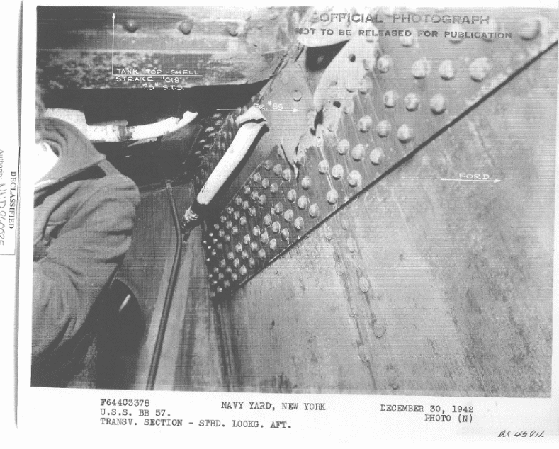
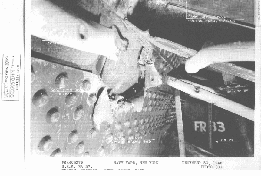
There are no inconsistencies with this estimate and the best estimate is by a 6-inch Type 4 Common projectile from Kirishima. The base fuze allowed the shell to penetrate the outer layer and it exploded on the next bulkhead.
31. An area of the 50-pound STS shell 24 inches in diameter at frame 87 starboard between the second and third decks was indented to a depth of six inches. It was reported this was a glancing hit by an 8-inch projectile. If so, the performance of this 50-pound STS plate was most unusual. Another possibility is that this indentation was made by the windscreen or cap head of hit No. 11 or No. 20.
One 14" hole in ship's side at frame 72 starboard, 5 feet above waterline. Dented in over a 6' diameter area.
This impact was estimated by BuShips to be either a glancing hit from an 8-inch shell or the windscreen and cap head of an 8-inch shell. We believe this estimate to be incorrect. Hit 4 showed that at these ranges that even an 8-inch shell traveling underwater could penetrate the outer shell. Next, most nose-fuzed HE shells exploding on impact at a small angle would have punched a hole into the plate rather than denting it as was the case for this hit. That this blow was at a small oblique angle can be seen in Figure 73. A 5.5-inch nose-fuzed shell would punch a hole in any plate less than 1.36 inches thick, which means that the actual 1.25 inch plate is too thin to have prevented this from happening. A 5-inch shell fired from a 5"/40 would have only left a dent, but we believe that this projectile is too small to have caused the size of dent actually made in this plate.
In BuShip's original report, the authors proposed that this damage may have come from the windscreen and cap head from either Hit 11 or Hit 20. However, these two hits came from a forward direction while Hit 21 came from astern, which therefore eliminates any relationship between Hit 21 and the other two hits. After eliminating these other possibilities, what we are left with is that this damage appears to have been caused by the impact of a cap head and windscreen from an AP shell. Further work is needed to determine the size of this projectile.
Looking at the two types of AP cap heads fired during this battle; the 8-inch AP projectile has a thick cap head that comes to a rather blunt, but distinct point, and is more like a blunt projectile nose tip than any of the other cap heads used in other sizes of Type 91 AP projectiles. This design was intended to allow the 8-inch shell to better penetrate the homogeneous armor that most US cruisers were armored with during the 1930's when this shell was developed. By contrast, the cap head of the 14-inch AP projectile has a forward face that is flatter with no point, being more discus- or mushroom-top-shaped. Examining other information about these projectiles brings out these values:
| Caliber (in) | Windscreen length (in) | Cap head | ||
|---|---|---|---|---|
| Diameter (in) | Thickness (in) | Weight (lbs) | ||
| 8 | 16.6 | 5.5 | about 5 | 7.9 |
| 14 | 26 | 12 | 8 | 63 |
These size differences between these two projectiles is also significant in that the 8-inch cap head is only 5.5 inches in diameter, is 5 inches thick and weighs 7.9 lbs. The 14-inch cap head is 12 inches in diameter by 8 inches thick and weighs 63 lbs. The struck plate is 1.25 inches thick, which is not an insignificant thickness. An area in this plate over 24 inches in diameter was pushed in to a depth of 6 inches. The shape of this dent matches the oval shape of the 14-inch cap head and the heavier cap head is by far more capable of pushing in this amount of steel than the much lighter cap head of the 8-inch shell. This damage largely matches the dimensions of the 14-inch cap head. Our conclusion is that Hit 21 was the result of a 14-inch Type 1 AP cap head and windscreen.
The shell itself seems to have missed South Dakota, either by going under her hull, if it could dive at the shallow angle of fall at these close ranges (circa 7 degrees is the minimum entry angle even for these specially-made diving shells), or after it skipped off the water itself, if not. This shell obviously came fairly close to South Dakota either way and, if it skipped off the water, perhaps it caused some of the less-than-well-defined superstructure damage noted (punching through as solid shot or as shell splinters after exploding in the air nearby due to fuze action after the ricochet). If so, it would be only the second 14-inch AP round to have hit South Dakota. Another possibility is that the shell ran parallel to South Dakota's hull as she turned away from Kirishima at 0110. For that possibility, the shell would have entered the water around frame 87 and loss its windscreen and cap head, which deflected into South Dakota's hull, and then dove and detonated around frame 56 near the bottom of the ship, causing seam damage to her hull. 61
32. This hit was just above the second level and above the house top at frame 87 on the starboard side of the structural longitudinal bulkhead and was estimated as a 5-inch projectile. This projectile pierced the foremast housing tube and passed through the port longitudinal structural bulkhead near frame 86. The port bulkhead stiffeners at frame 86 were distorted and the first aid locker was penetrated by three fragments. Five panels of sheathing and insulation in the first aid station were damaged.
1 8" hole, through after side of structural bulkhead, frame 87.
1 10" hole through both sides housing tube for radar mast, frame 87.
Lowering wire for foremast damaged.
1 4" hole through bulkhead plating at frame 86 port.
Bulkhead stiffener frame 86, punctured, twisted and distorted.
5 panels of sheathing and insulation torn out.
2-3" shrapnel holes at base of bulkhead just above bounding angles, frame 87 starboard.
3 shrapnel holes, through medical locker. Doors distorted beyond repair.
2" shrapnel hole through back of wash basin.
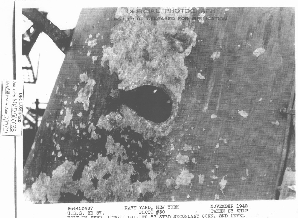
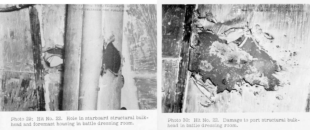
This shell detonated on impact, indicating a nose-fuzed projectile. The bulkhead is probably 25 lbs. or 0.625-inches STS or HTS plate based on similar hits on the exterior superstructure of the forward mast such as Radar plot. The timing of the hit is unknown, so the exact range and velocity of the shell is also unknown. The following analysis is meant as a rough estimate.
Using Equation 1, the calculations show that a 5.5-inch projectile striking at 1,300 fps would produce a 14-inch hole in STS plate 0.625 inches thick while a 5-inch projectile at the same velocity would produce a 9-inch hole in the same STS plate. This latter figure is closer to the size of the exterior hole in Figure 76 and slightly under the 10 inch hole seen in Figure 77. A 5-inch Type 0 HE projectile appears to be the best estimate for this damage and this is consistent with BuShip's original estimate. This shell came from either the 5"/50 caliber guns on the destroyers or one of the 5"/40 caliber secondary battery guns on Kirishima, Atago or Takao.
34. An estimated 8-inch AP projectile hit the radar antenna of 5-inch director No. 3. Fragments of the windscreen and cap head broke off and sprayed the starboard side of the stack hood in the vicinity of frame 89. The projectile pierced the stack hood and continued on through the radar antenna of 5-inch director No. 2.
[From list of fires]
Stack covers, base of stack. Repair 1 and 4. CO2 by repair party 1 would not put out this canvas but extinguish enough to double ignited portion of canvas underneath until Repair 4 arrived with hose. Paint on stack did not ignite.
Mount 7. A report was received in damage control that the upper handling room was on fire. Repair party 1 investigated; upper handling room was found flooded. No fire was found in this mount. A piece of wood from deck was burning outside, also parts of life jacket and mount bloomers. Those were quickly extinguished. This mount received a direct hit and first report was probably result.
Mount 3. Several reports were received at different times that mount 3 was on fire. No fire was discovered near this mount though at each report some small burning fragments would be found on deck.
There were numerous small fires on both the first and second superstructure decks on both sides mainly burning pieces of life jackets which re-occurred several times. Water would quickly extinguish but some small piece would flare up again. 64
[From list of damage in Enclosure D]
STACKHOOD AT FRAME 88
Forward Face – Shell hole 12" by 30" part of shell continuing through 4 partitions inside hood and out port side. All holes approximately 15" in diameter. Part of shell broke off after entering hood and went through 1 partition aft with a hole of 23" by 14".
Shell entered 2" from starboard side hood 4' above 07 superstructure deck. There were also other holes in forward face of hood of the following size: 6" diameter, 6" by 18", 2 holes 3" by 6", four holes about 2" in diameter, 2 holes approximately 3" by 8". Also 10 dents about 1" deep by 6" in diameter in forward face of hood.
Stack cover jack-stay on forward side carried away.
Deck in vicinity of frame 87 and 88 of 07 superstructure deck has 9 dents. 65
S.B. [Secondary Battery] Director #3
Radar elevation gear carried away.
2 legs of base carried away on left hand side. 65
Starboard side of stack hood between frames 90-96 – 4 holes approximately 4" x 6" between 05 and 07 superstructures.
Forward steam exhaust escape frame 96 between 06 and 07 superstructure. 8 holes 2" in diameter.
20 mm gun shield on 05 superstructure deck at frame 92 – 1 hole 2" in diameter near base.
Drainage line from Director 3 platform cut at frame 89 on the 04 level – hole 2" in diameter.
Athwartships bulkhead at frame 90 on 02 level – 5 holes approximately 2" in diameter. Also 5 bad dents.
Ready service box 20 mm at frame 91, 02 level – 5 holes approximately 2" x 8".
Ready service box 20 mm at frame 92, 02 level – hole 4" x 8".
Deck has 2 bad dents at frame 95 near stack – 02 level.
#1 motor whaleboat has 15 shrapnel holes.
Boat repair shop at frame 97-99, 02 level has two holes in overhead, 1 3" in diameter and 1 4" by 10".
Heater steam lines and ventilation supply duct B-0203E are cut by 4 shrapnel holes.
Nitrogen antenna lines T-12, T-13, and T-9 are cut by shrapnel.
Radio transmitter trunk T-7-H – 2 holes 2" in diameter.
Bulkhead 97 – 4 shrapnel holes in insulation and sheathing. 4 shrapnel dents in bulkhead.
WT door 02-98 has 2 holes through door approximately 2" in diameter.
Natural exhaust B-0205E at frame 100 has 2 2" holes.
Watertight door 02-100 to B-0205E (Battery Charging Room) has 3 holes, one 2" by 8", one 2" by 1" near top of door; and one 3" by 4" forward edge near the hinge.
B-0205E – hole in deck approximately 1" in diameter at frame 100.
Steam line pierced by shrapnel embedded in lagging or steam line, frame 100.
Many dents in deck, bulkhead, and overhead in compartment B-0205E.
Brass drain line for 03 deck level has hole approximately 1" in diameter at frame 100. 66
01 Superdeck Starboard Side.
Right-hand side of Mount #7 – Deck has been dished in 2" over a 20" area. Center of area 2' from after edge and 1½' from lower edge of plate. Seam out after right corner of mount opened up 3/8". Shows signs of intense heat. Armor is 2" thick. 60
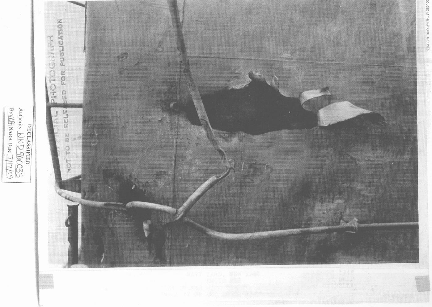
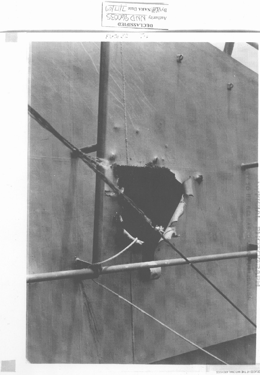
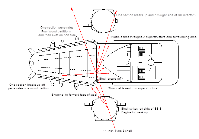
This damage is very inconsistent with an 8-inch AP shell especially as the shell did not detonate. This shell disintegrated on impact which sent large numbers of small pieces of shrapnel into the surrounding structures. This type of damage is more typical of a 14-inch Type 3 incendiary projectile. The only ship to fire this shell type was Kirishima. The shell began breaking up on Secondary Battery (SB) director 3 which sent some of the stays and incendiary tubes into the stack. Some of the incendiary tubes ignited at the base of the stack and around 5-inch mounts 3 and 7. The nose of the shell entered into the stack and then the shell probably broke in half and continued to break up within the stack with parts hitting SB director 2 and sent shrapnel all over the superstructure. We believe that what is being described in the damage report as pieces of life jackets are actually the small rubber thermite incendiary tubes from the Type 3 shell which are 1 by 3 inches in size. These tubes burned at low-order as the shell did not detonate properly. CO2 fire extinguisher gas would have had no affect on them due to their magnesium filler and they could burn as hot as 3,000 degrees Fahrenheit (1,650 degrees Centigrade), but for only 5 seconds. These tubes were quite capable of starting these small fires throughout the superstructure as described in the report. 5-inch Mount 7 reported that the armor shield had been exposed to extreme heat and 5-inch Mount 3 was reported on fire, but when fire fighters arrived they only found burnt-out fragments. Fires at the base of the stack but not at the point of impact are also an indication of incendiary tubes. For these reasons, we have concluded that the best estimate for this damage is that it was from a 14-inch Type 3 incendiary shell.
34. Five-inch mount No. 5 was hit a glancing blow by an estimated 6-inch projectile. The 2-inch STS was sprung but not penetrated and minor structural damage was sustained inside the mount. Apparently the projectile detonated on impact. Fragments gouged both guns of 5-inch mount No. 7 and sprayed the starboard side of the deckhouse on the first and second superstructure decks between frames 93 and 100.
Secondary Battery Group #3
... Mount 5 – Fragment gouged left gun, not serious.
Armor sprung with minor structural damage inside mount from glancing hit.
Mount 7 – Numerous gouges in both guns from fragments. Upper handling room damaged.
The starboard Boat Crane was also damaged from this hit.
Starboard Boat Crane:
Cables cut by shrapnel, cables completely ruined. Cross braces of crane cut in six places, and three others dented. Lower inboard arm has 2" x 4" hole, approximately in the middle of the arm. Upper inboard arm has 3" x 4" hole in same section. Two vertical braces have 1" diameter holes. One ladder rung carried away.
There are no inconsistencies with this estimate. The timing of the hit is unknown. The shell detonated on impact indicating a nose-fuzed projectile, probably a 6-inch Type 0 HE projectile. The other possibility as the timing is not known would be a 5.5-inch Type 0 HE projectile from one of the light cruisers.
Calculating for the larger of these two possibilities: At 6,000 yards, a 6-inch shell from Kirishima would be traveling at about 1,700 fps and the angle of fall would be about 4 degrees. The explosive filler for this shell was 6.5 lbs or 6.5% of the total shell weight, which puts it in the category of a normal World War II HE shell. Using the five steps for Equation 1:
-
(2.576 x 10⁻²⁰)(D) = 2.576 x 10-20 x 6 = 1.55 x 10⁻¹⁹
-
V5.6084COS[2(Ob2 - 45o)] = 1,7005.6084 x COS [2(45 - 45)] = 1.31 x 10¹⁸
-
(0.156)(D) = 0.156 x 6 = 0.94 inches
-
1.55 x 10-19 x 1.31 x 1018 = 0.20 inches
-
Tphe (noADF) = 0.94 + 0.20 = 1.14 inch thickness of STS which will result in a caliber-width hole
To find the minimum thickness of STS that ensures that no crack will be made in the plate (just a dent), we multiply 1.14 x 1.2 = 1.37 inches.
Note that this calculated thickness is less than the 2 inches of STS that was actually on the back of the mount. Thus, the denting with no cracks caused by this hit is consistent with a 6-inch Type 0 HE shell.
35. An estimated 8-inch AP projectile hit the shell at the second deck, frame 109-1/2. The projectile pierced the shell at a seam between a 25-pound and a 50-pound STS strake, furrowed through the 20-pound STS second deck, pierced 10-pound longitudinal torpedo bulkhead No. 2 and penetrated the 12.2-inch longitudinal armor bulkhead to a depth of 7 to 8 inches at the top edge of the armor. Fragments went aft and pierced and distorted frames 109-112 and penetrated the third deck between torpedo bulkhead No. 2 and longitudinal armor bulkhead. Although the hole in the shell was above the waterline, compartments B-71-F, B-75-V, B-77-F, and B-79-F flooded as a result of this hit. This was reported by South Dakota to have been a 6-inch projectile, but it is not believed that a 6-inch projectile would have penetrated so much armor.
South Dakota's action report only lists a five-inch entry hole at Frame 113, three feet above the waterline. 60
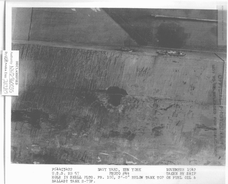
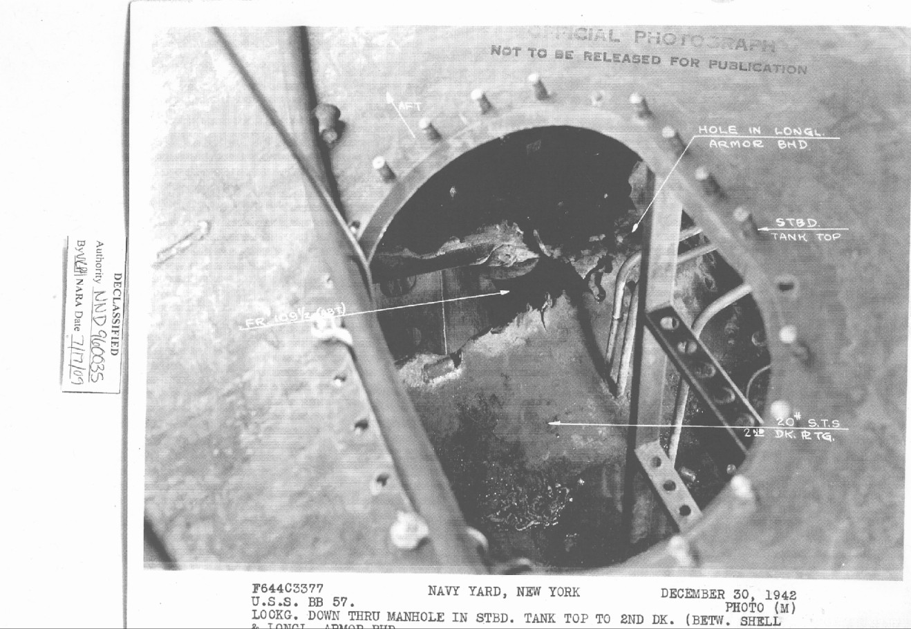
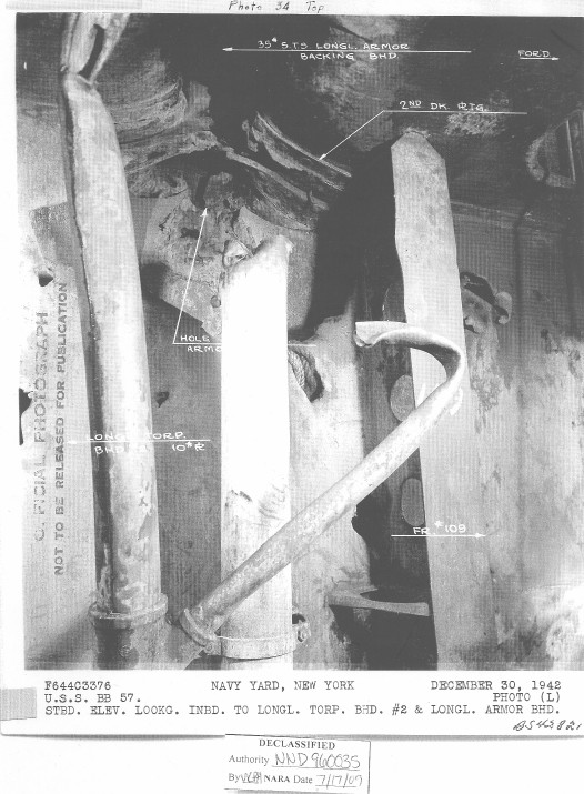
There are no accurate, documented measurements for this damage. The hatch shown in Figure 84 is 26 inches long which would allow us to estimate that the hole is possibly 11 to 12 inches wide. The pipes in Figure 85 are no larger than 6-inch and this gives us a crude estimate as to the size of the pit in the plate. Only two types of projectiles would be capable of digging into the main belt as shown in this photograph and they are the 8-inch Type 91 AP and the 14-inch Type 1 AP. Based upon the size of the impact holes, this damage appears to be from the 8-inch projectile. This AP projectile ripped through the outer shell, losing its windscreen and cap head in the three prior impacts before it reached the main belt. The shell body impacted the main belt at its edge and it appears that the shell shattered at this point. If it exploded, then the explosion was probably low-order.
The hard face of the plate failed due to the close-range, high-velocity impact shock and compression force so near the edge of the hard, brittle face material, which cracked and folded back the face there like a door on its hinge, but the shell did not penetrate the back layer because, one, it broke up as it penetrated the face layer (the 8-inch Type 91 AP shell has no AP cap and had already lost its cap head), which reduced its penetration ability considerably, and, two, the armored second deck was bracing the Class "A" armor plate edge and preventing any of the back layer from being forced out of the broken projectile's path.
A 14-inch Type 1 AP projectile would have done much more damage due to its true AP cap not being removed by the thin plates this shell passed through before it reached the belt armor. Loss of the cap head would have reduced the penetration ability of the shell somewhat, but at near right-angles and at this close range, this 14-inch AP shell would still have been able to punch entirely through the belt and gouge a deep notch in the edge of the armored deck prior to slowing to a stop and exploding. None of this happened and the holes shown are too small to have been made by a 14-inch shell. The best estimate for this damage is that it was made by an 8-inch Type 91 AP shell.
36. An estimated 14-inch projectile passed through both sides of hatch coaming 1-128 and detonated upon hitting the barbette of Turret III at frame 123-1/2 about 17 inches from the top. The 17.3-inch armor was gouged to a depth of about 1-1/2 inches over an area of 15 inches in diameter. Surface cracks covered this area and vertical cracks developed in the armor to a distance of 8 feet aft of the point of impact. The blast blew a hole in the main deck 3 feet wide extending around the barbette for a distance of 10 feet. Around the hole the main deck was dished down 8 feet from the barbette between frames 121 and 130. Some fragments were deflected down and aft riddling the starboard side of bulkhead 129 in numerous places between main deck and second decks including one hole 26 inches by 35 inches. Some fragments continued on through C-204L on the starboard side of the barbette considerable damage was done to equipment, mess tables, and ventilation ducts. The armored second deck defeated all fragments. Fragments and blast deflected upward from the point of impact demolished gas seal and water shed for 30 feet around the circumference of the barbette, gouged the gun sleeves of the right and center gun of Turret III and ignited the gun bloomers. Some difficulty was experienced in training the turret after the hit but it was believed that the turret was still able to fire. Fragments ranging aft on main deck damaged 20 mm guns, ready service boxes, gun shields, starboard catapult, and fire plug 1-133-2. Other fragments spreading forward pierced the superstructure on the main and first superstructure deck.
[From "Summary of Outstanding Events" section of Action Report]
All batteries ceased firing after 0110, shortly after turret three reported training trouble because of a shell hit somewhere near the gas seal ring. This hit was later identified as a fourteen inch shell hit from fragments recovered in that area, and the size of the indentation in the barbette. 69
[From "Chronological Log of the Battle" section of Action Report]
0110Engagement broken off, proceeding at full speed on course 235°T. Ship's repair parties and personnel not essential at damage stations fighting fires, caring for wounded and estimating damage done.
Observed splashes on wake 1000 yards astern. No enemy ships observed firing. Possibly one of those left burning. 70
[From "Enemy Forces" section of Action Report]
The column of four ships which illuminated the SOUTH DAKOTA sustained heavy casualties. The leading ship, presumed to be a battleship, was seriously damaged and undoubtedly set on fire. It may be that this ship fired its last gesture salvo at SOUTH DAKOTA which scored a fourteen inch hit on the barbette of turret III at the end of the action. 71
[From list of fires]
22. Bloomers, Turret III, ignited by hit in barbette. Extinguished by decontamination party. 59
[From list of damage in Enclosure D]
Deck and starboard side of turret 3 between frames 121 and 130, 8' out from turret, are bent down next to turret. Hole beside turret in this area is 3' wide by 10' long with the center of the hole about frame 123.
Hatch coaming of hatch 1-122 has a semi-circular cut on both sides 15" deep.
Ventilation intake for system 3-126 has screen blown in.
Deck between frames 110 and 134 are splintered by shrapnel.
Starboard side of #3 barbette has plating dished in 1½" over an area of 15" in diameter aft of seam. Circular cracks extending over this area. Vertical cracks extend aft 8' around barbette.
Davit holder besides hatch 1-128 bent and twisted.
Hatch coaming around hatch 1-128 is torn, twisted, and cut by many pieces of shrapnel.
Gas seal on turret 3 torn and twisted for 30' on front of turret.
Gun 3 slide pitted with shrapnel.
Two ladders torn from turret base.
Ammunition box aft of turret 3 and by starboard 20 mm gun shields pierced by shrapnel and all bent and twisted.
Amidships splinter shield has 4 holes that are 4" in diameter.
One hole 12" by 14" and one hole 10" by 10".
Fire Plug 1-133-2 sheared off at plug.
30 caliber airplane ready ammunition box at frame 133 completely wrecked.
Starboard aft 20 mm gun wrecked. Spare barrel holders torn off shield. Ammunition boxes torn and twisted.
Recovery boom and vertical brace cut by shrapnel.
40 mm deck plates badly warped and buckled, port and starboard.
Hatch 1-139-1 and scuttle badly warped and twisted. 72
SECOND DECK
[Second deck bulkheads 136 to ships Scullery at frame 129]
Watertight door 2-136-1, hole 2" by 1", 6" from bottom.
1" hole 2' from top through sheeting.
Frame 136 – hit by shrapnel. 2 bad dents beside door in "I" beam. 3" x 1" holes 2' to port of door 2-136-1, 3" from deck.
Bad dent 1' above "I" beam, dented just above deck. Bad dent 4" in diameter 1" deep beside door, 3' above deck, wire cable cut above door next to overhead. Also hole 4" x 1 ½". Ventilation supply C-322L pierced by shrapnel. 2 holes in line with door 6" by 10" in diameter. Another small in duct 6' above deck.
2 bad dents in supporting stanchion at frame 134 starboard, at edge of scullery.
Air deflector broken by small pieces of shrapnel, starboard side aft of galley.
10" by 2" hole after starboard corner of scullery just above deck. Steam line through starboard side of compartment has several holes in lagging, also may be in the lines.
Stanchion at frame 131, starboard side of scullery has two dents 1½' above deck. 4 holes in scullery, 19" by 3", 2 x 1" holes and 1 ½" by 4" hole. 72
[Second deck around door 2-129-1 and barbette]
4 steam lines carried away, 2 temporarily repaired. Large hole starboard side of door 2-129-1, is 26" by 38". 11 other holes at this side of door in same area are about 10' by 4' from deck.
Watertight door 2-129-1 bent and cut and is damaged beyond repair.
Door frame 2-129-1 bent and bulkhead and side of door frame dished in 6". 3 holes near deck 3' from starboard of door are 12" by 4" and 10" by 3".
Inboard table leg in scullery at frames 129 cut and bent.
2 steam lines to coffee urn damaged. Coffee urn has 2 holes 1" x ½" and also many small holes.
Lagging of large steam line on overhead torn at frame 128.
2 "I" frames starboard side of door 2-129-1 badly cut and dented with one pushed against bulkhead.
Air escape for C-917V bent and distorted and almost flattened in some spots. Lagging on large steam lines on overhead torn at frame 128.
3 "I" frames on port side of door, one is slightly dented, one is badly bent and dented to port side and the other is cut and bent.
Several electrical cables cut just above deck at frame 129 and cable cut 7' above deck and above hatch 2-128. 1 steam and one fresh water line cut in this area.
4" x 2" and 1" diameter holes in 440 power panel (2-128-1).
Hole in back panel and dent in bulkhead. 2 electrical cables cut beside hole.
20' of exhaust C414T carried away. The remainder pierced by numerous pieces of shrapnel.
Exhaust system 3-126, 10' carried away between deck and overhead beside turret. Remainder badly bent and cut, 15' area.
Supply duct C-201L pierced in 2 places. One hole 10" x 12". One hole 2" in diameter.
Frame 127. Motor blown off one power shell hoist. Hoist half way off track. Roller track badly bent and out of line.
20' of mess tables around barbette missing. Also angle iron supports missing.
Hatch 2-128-2 retaining edge for gasket badly distorted and cut on starboard side.
Curved I beam around barbette. 10' carried away from frames 123 to 125. Distorted and cut 20' forward and 10' aft.
Armored deck bent down 4' into compartment. Hole beside barbette 2 ½' by 12'.
Bounding bar cut and bent 20', (1" by 3").
Two (2) degaussing cables badly cut and torn.
Drain line beside hatch 1-122 cut in two places by shrapnel.
Wire cage pierced in two places around ladder. Switch box on cage broken.
Supply vent C-603E, one 1" diameter hole.
Supply vent to C609E badly bent, also ripped near overhead.
Fire main above plug 2-119-1 pierced by shrapnel. Hole 2" x 1".
Nozzle and bracket bent by shrapnel.
Hole in Galley bulkhead 119, 7' above deck, hole 6" x 4".
Frame 114, centerline 3rd deck, 1 electrical cable cut by fire.
Frame 113, overhead starboard side hatch 3-113-2 – 2 electrical cables cut by fire.
Circular cracks area 6" below deck main deck, frame 122.
Water seal above main deck dented and pulled away from rivets 4' at frame 125 starboard side of barbette.
Athwartship "I" beams – frame 123 and 126, beams damaged 8' from barbette at frame 125, bent twisted 4' x 6' more slightly bent down from deck.
Vent motor at frame 121 damaged.
Scuttlebutt damaged at frames 122, several holes in top. Small pieces shrapnel hit motor and compressor below. 73
GUNNERY DAMAGE
[Damage to gun turret # 3]
Turret #3.
Received hit by 14" projectile in armor about 17" from top of barbette on starboard side. Turret was trained in this direction. Projectile was deflected downward through deck. Fragments caused damage as follows:-
Gas seal and water shed disrupted.
Sleeve of right gun badly scarred and gouged so sleeve was removed to make gun serviceable.
Gun hoop received shallow indentation through sleeve.
Center gun sleeve gouged but still serviceable.
Right and center guns – securing strips for bucklers damaged. 35
[From list of equipment damaged or destroyed by gun fire]
The depression stops on #3 turret were moved out of position by shell fire, therefore the D.S. [Depression Stop] circuit in #3 turret was made inoperative. 74
South Dakota's action report lists the following damage to the Starboard Catapult which, as noted above, BuShips reported as being caused by Hit 26:
Starboard catapult cable cut by shrapnel. Shrapnel holes through catwalk, and aviation fuel hose rack torn off. Track badly damaged. 72
Starboard catapult requires new saddle and cable. Spares are aboard.
Port catapult struck by projectile should be replaced as inboard track is bent beyond repair. Cable and sheave destroyed also. 75
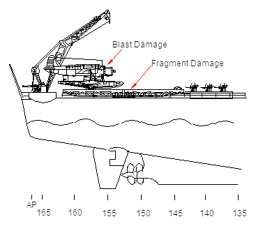
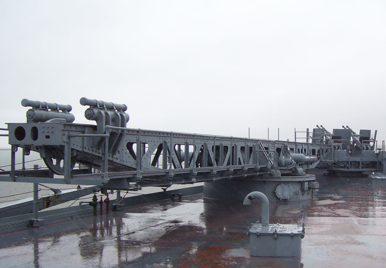
This hit was from the last or one of the last salvos fired by Kirishima and her gunners deserve credit for still making their shots count even though their ship was wrecked and on fire by this time. The description of the damage for this impact was written in a difficult way to follow and only two photographs were used in the original BuShips report to illustrate the damage from this hit. There has never been a question as to caliber of the projectile that caused this damage, estimated by BuShips as 14-inch, but the type of 14-inch projectile was not given in the damage report.
The original authors of the BuShips report probably only used the two photographs they supplied in their report to make their conclusions. The first line in their report makes the association that the shell passed through both sides of Hatch 1-128 and then struck the barbette. However, the South Dakota's action report does not mention the hatch. In addition, there are two hatches, 1-122 and 1-128, that are listed as damaged in the report without any notes as to the causes of the damage, so once again the damage report is very confusing in the way it was written. By using more USN photographs of the original damage along with some recent photographs taken aboard USS Alabama of these same areas, we hope to be able to place into context what was really damaged by this impact and what type of shell caused it.
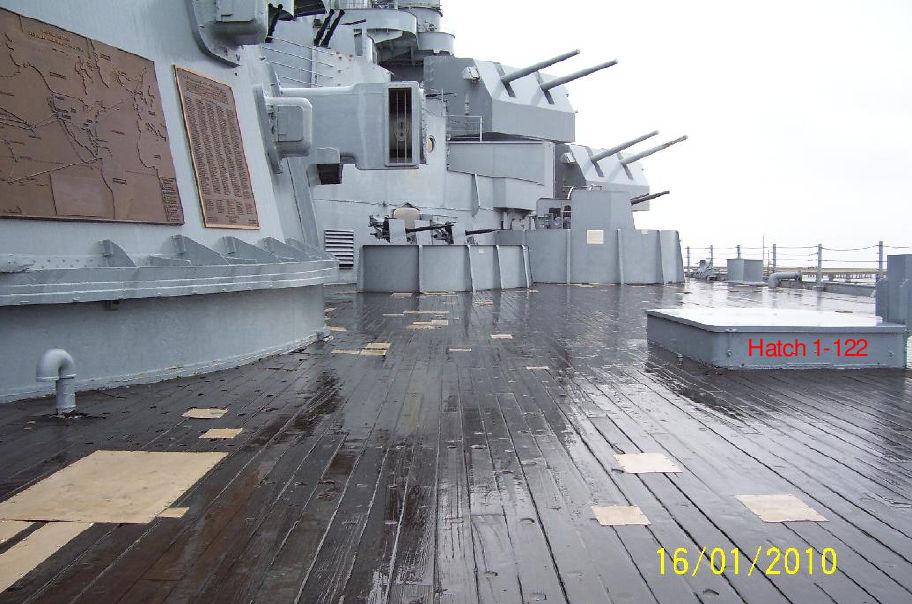
The photograph in Figure 88 was taken aboard USS Alabama and shows Hatch 1-122 in relation to Turret III. The damage listed in South Dakota's damage report is that there was a 15-inch deep semi-circular cut on both sides of the hatch. Though the BuShips report labeled this hatch as 1-128 in their report, most people believe they were actually referring to Hatch 1-122. Hatch 1-122 measures 56 inches wide x 96 inches long by 12 inches high. The forward edge lines up with frame 122 with the center seam of the barbette at frame 123.5. The aft side of the hatch is at frame 124. The distance from the inboard side of the hatch to the barbette is 118 inches. This matches the copies of USS South Dakota's builder's blueprints which were used for the damage report. The flange seen over the barbette is 7.5 inches wide and the distance from the deck to the bottom of the flange is 21.0 inches. The total height of the barbette measured from the top of the flange to the main deck is 28.5 inches at the center seam or frame 123.5.
The photograph in Figure 89 was also taken aboard the USS Alabama and shows the relationship of Hatch 1-128 to the forward edge of the barbette. The damage listed for this hatch in South Dakota's report is as follows:
"Davit holder besides [sic] Hatch 1-128 bent and twisted. Hatch coaming around Hatch 1-128 is torn, twisted, and cut by many pieces of shrapnel."
The forward edge of this hatch lines up with ship Frame 128. The barbette itself runs from frames 118.5 to 128.5 and each frame is 4 feet wide.
This photograph of South Dakota (Figure 90) shows that the forward flange, normally at the bottom of the turret face, has been destroyed and the steel bent up, which means that the blast occurred underneath the flange. In addition, two of the ladders have been blown off the face of the turret. Only the far left ladder remains attached of which the lower legs can still be seen on the right side of Figure 90. The turret in this photograph has been turned back to the centerline, which is why there is no deck damage seen in this photograph. The bloomers were reported to have caught fire after the explosion.
Figure 91 shows the damage to the right gun sleeve, which has been removed to make the gun serviceable. The damage to the gun sleeves and lack of damage to the gun barrels themselves indicates that the blast took place directly under these components. In all likelihood, the right gun was directly over the blast and the blast was then directed up and against the barbette itself. The right gun hoop received shallow indentations through the sleeve due to the fragment damage. The center gun sleeve also took damage but the gun was able to remain in service.
Figure 92 was not used in the original report but is the best photograph of the damage that we have found. This photograph shows the area around Turret III above the main deck and shows that the barbette actually has two impact scars. The lower scar is deeper and represents the 15-inch x 1.5-inch deep scar noted in the report. The upper scar is a surface blemish with the center approximately 17 inches from the top of the barbette. This indicates that the original BuShips authors are applying measurements from two separate impacts as if there was only one. This photograph is looking aft with the turret now trained to the centerline. The impact is just aft of the center seam of the barbette where two 17.3-inch plates come together and the impact dislodged the joint between these two plates 8 feet down the barbette.
The lower impact seen in this photograph is below the main deck level and the steel deck is bent down in this area. The hole is directly up against the barbette and there are two measurements within the original documentation for the size of the hole. These are 3 x 10-feet and 2.5 x 12-feet. The original authors also estimated the hole was caused by the explosion but without the use of this photograph they could not see how the wood deck overhangs where the steel is bent down. This is an indication that the steel was pushed down from under the wood prior to any explosion. The shape of the hole and it being directly up against the barbette are important clues to determining just what happened. In addition the riveted structure between the barbette and the deck supports has been pulled away and down, popping the rivet heads but leaving the steel strakes intact. There are no apparent fragments that penetrated the 1.5-inch STS steel.
The area of wood planking damage seen in this photograph is relatively small. There are about 14 or 15 four-inch wide planks shown damaged in this photograph, giving a width of 56 or 60 inches of damaged deck area as noted in Figure 92. There would be 7 planks remaining before the outer limit of the hole is reached so this means that the hole is approximately 28 to 32 inches wide, which is close to the 2.5 foot x 12 foot measurement given in South Dakota's action report. Looking closely at the lower scar, there is a vertical scar from the top of the dent and a different color line that runs through the top of the dent which will help identify this impact scar in other photographs. The different color line that runs through this scar also marks the lower edge of a circular 15 inch x 8 inch I-Beam that supports the main deck, which will help estimate the distance below the main deck that the center of the lower impact was. The lighter color band on the barbette is where the main deck was pressed up against the barbette and marks the original deck level. Based on the documentation in the reports, the deck and Athwartship I-beams 123 and 126 underneath was bent down out to 8 feet from the barbette and then severely bent down the last 3 feet.
Figure 93 is a close up of the upper scar damage to the plate. This photograph was used in the original BuShips report and may have been the only one of two that the original authors used. The top of the flange at the very top of the barbette can be seen in the upper right corner of the photograph. The vertical seam and right side gouge can also be seen along with the lines that marked where the main deck used to be. This scar did not significantly dent the armor and resulted in surface flaking of the plate with deeper cracks at the center. If viewed by itself this photograph would suggest that the impact was made by a HE shell due to the lack of damage to the plate surface.
Figure 94 is the second photograph used in the original report. This shows the lower impact site looking up from the 2nd deck level. The photograph is looking aft and shows that Athwartship I-beam 126 has been bent down and the remains of the circular I-beam it supported that surrounded the barbette. The main deck has been pushed down and the center of the lower gouge (marked with an X) is approximately 4" below the original line that marked the bottom edge of the circular I-beam. It also shows circular cracks on the surface of the Class "A" plate that radiate out from this impact and a minor vertical scar at the top of the gouge which can be seen in the photograph looking at the scars from above the main deck. These are the circular cracks documented in South Dakota's report, which is quoted here: "Starboard side of #3 barbette has plating dished in 1.5" over an area of 15" in diameter aft of seam. Circular cracks extending over this area."
Concentric cracks in the brittle face of Class "A" armor are virtually always seen when a face-hardened plate is impacted hard enough to make a significant dent or hole in it. The surface layer is extremely brittle and the shock waves rippling outward along the face and those going into the plate and reflecting from the plate back or hard-face-to-soft-back plate boundary cause a Moiré (interference) Pattern on the surface where they null and reinforce each other, which is why the cracks seem to be so evenly spaced. This is a very important clue because it shows that the 17.3-inch Class "A" plate took a major shock below the normal level of the main deck. These cracks show that the shell body impacted here and not at the upper scar at 17 inches below the top of the barbette.
The center of the impact is approximately 4 inches below where the original bottom edge of the circular I-beam that supported the main deck was. This places the center of the lower impact at 20.5 inches below the top of the 1.5-inch STS steel weather deck and this is approximately 51 inches from the top of the barbette as measured from the top of the flange to the center of this impact site.
Figure 95 above is looking a bit forward. The lower impact scar is hidden due to the distorted main deck, but this view shows Athwartship I-beam 123 and how it is bent down. Also shown are the remains of the circular I-beam it once supported. You can still see the faint circular cracks along with the center seam between Class "A" plates.
This closer look in Figure 96 shows how the riveted structure between the circular I-beam and the barbette was pulled apart with many rivet holes remaining intact. This view also shows how the circular cracks crossed over the seam between the two plates and that the circular I-beam itself was twisted and ripped in half. Athwartship I-beams 123 and 126 were bent down 8 feet out from barbette with the last 3-4 feet being severely bent down.
The following photographs were taken aboard sister-ship USS Alabama to give an idea of how the same area on USS South Dakota would have looked before the battle.
Figure 97 shows Athwartship I-beam 123 which is seen supporting the 15 x 8 inch circular I-beam that surrounds the barbette. The small angle irons seen attached to the circular I-beam are supports for the mess tables that surround the barbette and do not imply any vertical support for the circular I-beam itself.
Figure 98 shows the gap between the circular I-beam and the barbette itself. The riveted structure attaching this I-beam to the main deck will be ripped down as seen in the damage photographs. The deck is not directly attached to the barbette but is sealed with a weather seal and pressed up against the barbette. The upper strength decks of the hull girder (main and second deck) are relieved of supporting the massive weights of the turrets. These weights are taken up by the platform decks, the ships sides, and the keel. In this way when the ship sags or hogs the upper strength decks are not bent by these actions. The armored weather deck, by being pressed so tightly up against the barbette, assists in holding the barbette structure rigid from lateral movements like when the ship heels or rolls. This however does leave a natural weak spot where the deck can be pushed down if the impact is heavy enough.
Figure 99 was taken on board USS Alabama looking aft and shows bulkhead 129 and doorway 2-129-1. The equivalent compartments on USS South Dakota were heavily damaged by shell blast. This photograph also shows the ceiling filled with ventilation ducts and piping and 20 feet of mess tables with their support structure, all of which were badly damaged or destroyed when this shell exploded. A large percentage of the fragments from this hit were thrown aft towards bulkhead 129 with a very few fragments traveling sideways or forward.
Figure 100 taken aboard the USS South Dakota shows the damage to bulkhead 129 and the size of the fragments. The large hole is probably the 26 inch x 35 inch hole documented in the report. There appear to be scars on the armored second deck where fragments were deflected through the bulkhead. The I-beams have been twisted and some cut.
Figure 101 taken on USS Alabama is of the same bulkhead. Note that even the vertical I-beams that make up the bulkhead are in identical locations. The two ships are framed identically around the turret with frame numbers painted on the hull and doors being labeled with identical numbers that match the South Dakota's damage report. The hatch leading to the third deck is Hatch 2-128-2. On the main deck Hatch 1-128 is directly above this hatch.
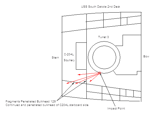
Figure 102 and Figure 104 show the ship's scullery on the opposite side of Bulkhead 129 as seen on board USS Alabama and give an idea of how the same area on USS South Dakota may have appeared.
Figure 104 shows the scullery looking aft. The wire screen is at Frame 131. Fragments ripped through this area damaging the kitchen supplies.
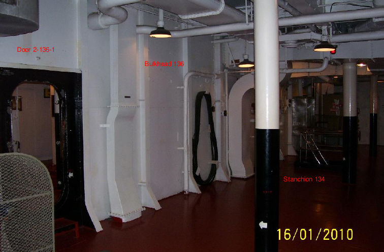
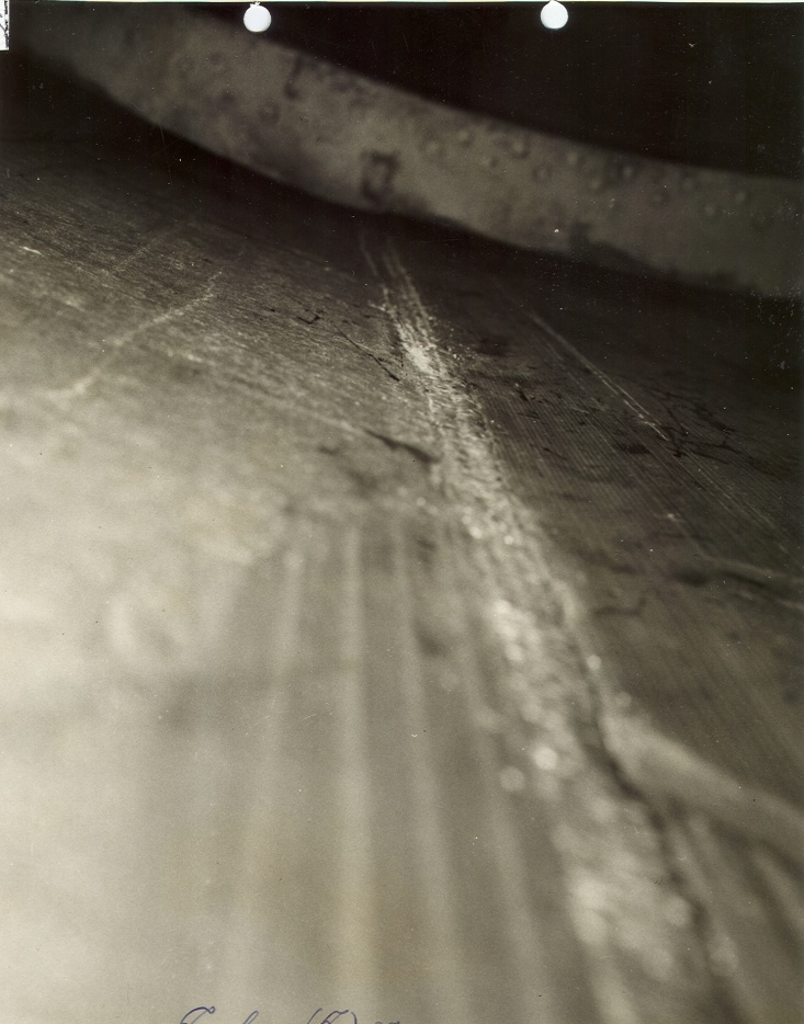
Figure 105 shows the compartment aft of the scullery. Both Stanchion 131 and Stanchion 134 on South Dakota took damage as did the ventilation ducts seen in the overhead.
Figure 106 shows Bulkhead 136 and Door 2-136-1 which were both damaged by fragments. Bulkhead 136 was the farthest that any fragments traveled from the blast point on the barbette, some of which penetrated this bulkhead.
Figure 107 shows the center seam between Class "A" plates within the barbette and the twisted and bent roller path that gave the turret difficulty in training after the battle. This damage was most likely caused by shock either by the impact force or by the explosion transmitted through the 17.3-inch Class "A" plate that protected the roller path.
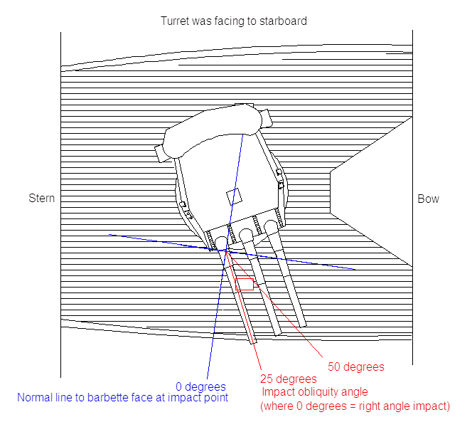
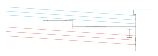
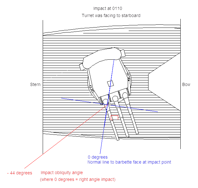
Determining the true shell trajectory was one of the first obstacles for the analysis of this impact. BuShips assertion that the projectile passed through Hatch 1-122 and then struck the barbette gives us two impact points on the ship from which we can determine which impact obliquity angles were possible and then using the track chart for the ships movements determine the range and time Kirishima, the hatch, and the barbette line up. The hatch begins at Frame 122 and ends at Frame 124. The center seam of the barbette is at Frame 123.5 with the projectile hitting the barbette just aft of the center seam. Zero degrees is the normal line to the barbette face at a right angle to the impact site. For the shell to pass through this hatch and strike where it did on the barbette, it can be shown that the range of possible impact angles runs from +25 to +50 degrees as illustrated in Figure 108.
The times that Kirishima, Hatch 1-122 and the barbette line up are between 0101-0103 with the maximum range of 7,500 yards to as short as 5,600 yards At 7,500 yards the angle of elevation is 4.0 degrees and angle of fall 4.63 degrees. At 5,600 yards the angle of elevation 2.89 degrees and angle of fall 3.23 degrees. 76 After 0103 Kirishima, the hatch and the impact site will never line up again based on the two ship's track charts. This is the first inconsistency. Captain Gatch was very specific that this impact occurred at 0110 near the end of the engagement. Either the impact occurred earlier than Captain Gatch knew or the shell trajectory did not pass through the hatch.
If the projectile impacted the upper scar implied by the original BuShips report and if South Dakota was on an even keel (no documented turn between 0101 and 0103), then with a 4 degree angle of fall a 14-inch projectile will miss the hatch entirely. The light blue lines in Figure 109 represent a 14-inch shell impacting the upper scar and the red lines represent it impacting at the lower scar. In the case of the lower scar, the shell would have impacted the deck prior to the hatch. 77 It is, however, the lower impact scar which is the main impact site. The gouge is 1.5 inches deep with the major shock cracks radiating out from this site.
In fact, there is no trajectory at the ranges where this battle took place which will allow the hatch to be hit and the projectile impact the barbette where the photographs show us it occurred and still duplicate the damage documented in the reports. It becomes clear that the original assertion made by BuShips that the shell passed through Hatch 1-122 on its way to the barbette must be incorrect.
If the impact was truly at 0110 as reported by Captain Gatch, then at this time Kirishima has passed South Dakota and has turned north in her attempt to withdraw. At 0107 Kirishima begins circling to port out of control due to damage to her rudders. South Dakota is on a course of 285 degrees true and orders her maximum (flank) speed at 0102 to avoid gunfire. At 0110 she turns from 285 degrees to a new course of 235 degrees true so she can withdraw from the battle herself (see ship's track chart in Figure 69). Based on the track chart, Kirishima is approximately 11,350 yards away at 62 degrees true bearing from South Dakota just before she makes her turn. The angle of fall at this range using extreme wear for the liners is 8.1 degrees.
The new horizontal impact obliquity angle on the barbette for the lower pit is circa 44 degrees. This is from the computation that Kirishima is 62 degrees true from South Dakota and South Dakota is on a course of 285 degrees true, which gives an angle of 62 degrees - (285 + 90 - 360 for the transverse centerline of the barbette at right angles to the wood deck planks) - (3 degrees for the actual impact point on the barbette a few feet aft of this centerline) = 62 - 15 - 3 = 62 - 18 = 44 degrees horizontal impact obliquity on barbette face. This scenario is shown in Figure 110.
South Dakota is making a port turn at this moment at flank speed. She will heel over to starboard as she turns to port from 285 degrees to 235 degrees. The two following photographs show USS Indiana making a similar high-speed turn – this one to starboard and heeling over to port. We estimate that the absolute maximum heel angle for the South Dakota class battleships under these conditions was 9.5 degrees.
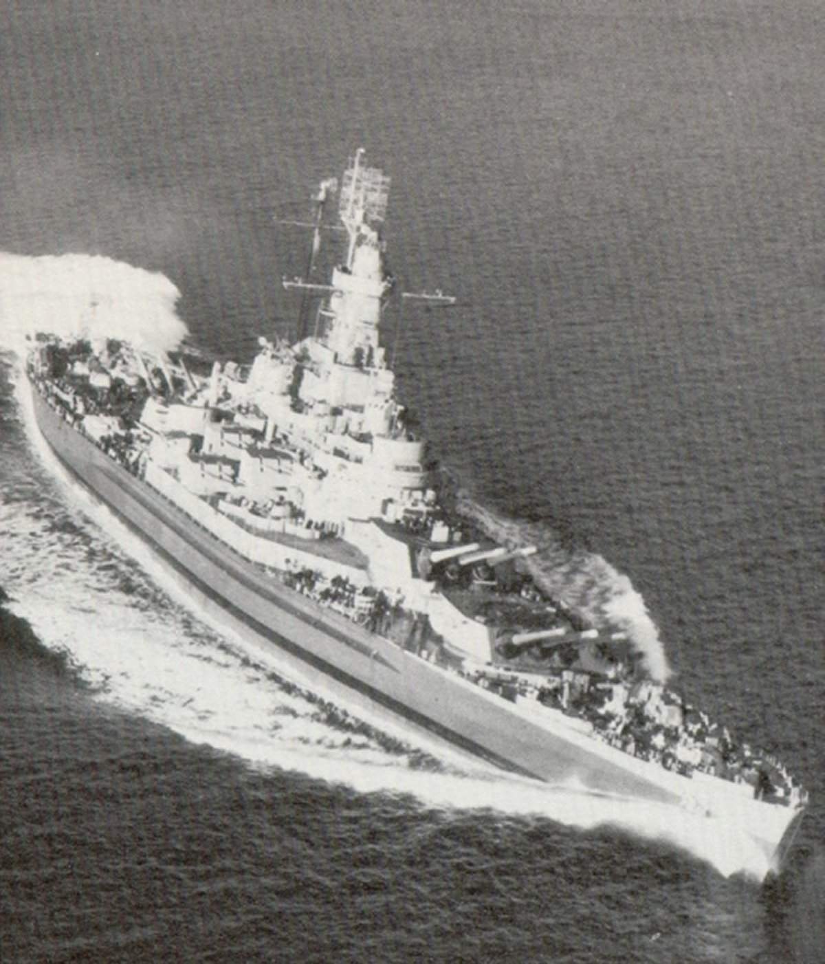
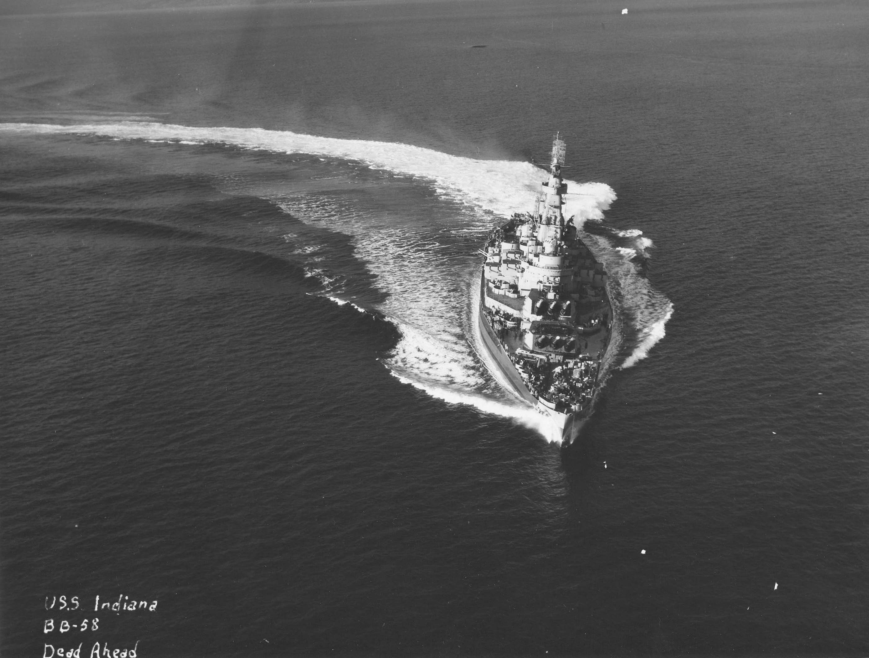
At this range of 11,350 yards, the angle of fall is 8.1 degrees (EB6.0G calculation), so the total angle is 9.5 (heel angle) + 8.1 (Angle of fall) = 17.6 degrees. Since the impact angle is now 44 degrees offset in the horizontal plane, coming from the stern the shell would impact the main deck about 78 inches from the barbette and strike the barbette approximately 24.7 inches below the steel deck (78 * TAN(17.6) = 24.7 inches). However, the impact resistance with the deck will also force the nose of the shell up approximately 3.0 inches and this places the center of the impact at the lower site to within 1.0 inch of our estimated depth. We used a worst case scenario, however, the effect of such small variations can be easily compensated by the spread in other estimated values, such as the possible upward curve of the nose due to the deck – perhaps it was 4 inches and not 3 inches, which would compensate for a steeper heel angle, or 2 inches which would account for a lesser heel angle – or else the shell was yawing slightly due to the worn gun, so the nose was tilted down about a degree, adding to the effective angle of fall (at small angles of yaw, a yaw of 1 degree can be replaced by an actual change in the trajectory by 0.5 degree in that direction with similar effects on the penetration calculations). Thus, for every minor tweak in one direction, we could have a tweak in another direction. The fact that this worst case scenario comes within 1.0 inch of our estimated depth shows that the principles used for this trajectory are valid.
The best estimate for the shell type that resulted in this damage is a 14-inch Type 1 AP projectile. The main deck was not blown down due to an explosive force but pushed down by the weight, velocity, and frontal density of the projectile impacting the deck. The wood deck overhang seen in Figure 92 again shows us how the steel was pushed down from under the wood. The shell impacting the deck approximately 78 inches away begins to bend the deck down and tear the weather seal and riveted structure away from the surface of the barbette. A simple analogy is the pull tab on a large soup can. When you lift the tab up the front edge of the tab forces the lid's lip into a large "smiley-face" arc. In the case of the barbette, the arc is in the opposite direction because the deck is outside the barbette and the lid for the soup can is on the inside of the can but the principle is the same.
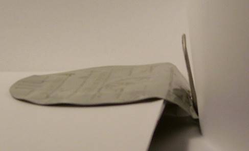
When the shell impacted the deck it would lose its windscreen, cap head, and AP cap due to the extremely high obliquity impact with the 1.5-inch STS deck. However, the cap head and AP cap, continuing along, but now at a shallow upward angle (the shell's 44-degree horizontal obliquity angle to the lower barbette impact point) would bounce off the barbette above the deck level near the upper blemish point (which had not been formed yet) at almost exactly 90 degrees from the original direction of motion – for an impact that does not penetrate deeply, as these light-weight cap pieces could not against the hard, thick barbette face, the angle of reflection is very close to the incoming angle, just going the other way on the far side of the normal (right-angles) line through the impact point, which turns out to be in a direct line with Hatch 1-122. Thus, they hit the hatch moving away from the barbette and slightly upward, causing the semi-circular holes in the hatch as they fly outward to end up in the ocean. As the remaining shell nose and body moved forward and down, it struck the barbette at the lower impact site. However, at 44 degrees, this angle is much higher than the test proof angle for a Japanese Type 1/91 AP shell (any size), which were only proof tested to 20 degrees from right angles, resulting in the projectile having its nose tip snap off and eliminating any possibility of penetrating the barbette more than the tiny 1.5 inch deep notch at the lower impact site. 78 Usually, this nearly horizontal impact would cause the projectile to ricochet slightly downward and mostly sideways away from the barbette, much like the AP cap and cap head mentioned above, but the deck prevents this motion by pinning the projectile nose to the barbette in the horizontal direction. The nose bends the deck away from the barbette as it tries to ricochet, but it is constrained to move almost straight down by the deck resistance, since this is the only direction that the deck will (relatively) easily bend under the force of the projectile nose from above. The result is the 28 to 32-inch width of the slot between the barbette and bent-down deck edge in the center where the projectile impact was, narrowing like a smile in either direction parallel to the barbette face until the deck is no longer bent at roughly 5-6 feet to either side of the projectile impact point.
The lower body of the projectile pivots up as the nose is forced down until the projectile is, in effect, standing on its nose with the broken tip sticking into the space beneath the bent weather deck and the base slammed up against the barbette near that upper "blemish" point just below the turret. This base-end rotation is so fast and violent that it is like a baseball bat hitting a home run (a rather extreme form of "base slap," as this lower body impact against the armor is termed in the US Navy). Since the armor's 1-inch-deep "cemented" face is about 650 Brinell hardness (approaching the hardness of hardened machine cutting tool steel), backed up by a circa 35% deep face of circa 500 Brinell, then another 20% dropping in a ski-slope curve to the circa 225 Brinell ductile back layer to the back surface of the plate (this last of "merely" bank vault steel hardness), the barbette armor face is essentially absolutely rigid and the rather soft lower body of the projectile flattens out against it as if the projectile was made from soft clay. A comparison of USN and Japanese hardening patterns for 14-inch AP projectiles is shown below in Figure 114.
This base slap causes the lower body to crush the explosive filler in from the barbette-impact side, where there is virtually no anti-shock cushion – only the upper end of the filler cavity has a heavy cushion to protect the filler from detonation on impact against thick armor head-on – for the very sensitive circa-1.5% (by weight) TNA filler. This causes the filler to detonate like British "Lyddite" (Japanese "Shimose") explosive did under similar impacts during World War I, acting just like it had been set off properly by a base fuze. This contact blast with the barbette at the upper blemish mark forms the surface damage pattern shown in the picture of that upper damage area on the barbette, with its irregular shock cracks and the small dislocations of the armor plates that have a joint very close to this spot (this is what caused the turret to be considered out of action due to the roller bearing path at the top of the barbette being misaligned, making turret traverse difficult). There is, however, no dent or pit in the barbette face at this upper blast point, it being merely slightly flattened and actually looks polished as the blast scoured off any surface lumps and removed the paint there.
This rotation and base slap is similar to what occurred for Hit 17. In both of these hits, the projectile nose failed to penetrate the final plate hit (the barbette for Hit 26 and the rear of gun mount for Hit 17) and the projectile nose was locked to the plate face (by the bent-down deck for Hit 26 and by being partially punched through the plate in Hit 17) at or near the initial impact point at a high angle (yaw angle circa 45 degrees in Hit 17 and obliquity angle in Hit 26) and rotated to end up broadside to and slammed up against the plate face (vertically nose-down in Hit 26 and horizontally nose to the right in Hit 17). In Hit 26 the shell slammed up against the unyielding barbette face and detonated and in Hit 17 it made a shallow dent in the thinner, ductile gun mount armor and remained intact. We think that these results against the plates that finally stopped the shells are very similar, regardless of any motion prior to the final impact.
With half of the shell below the main deck and the other half above the main deck and the shell in a vertical position pressed up against the barbette, we get the above main deck fragment pattern described in the report. The right gun was probably directly over the blast point with the base fragments being blasted up into the gun sleeve.
The fragment pattern below the main deck is largely traveling aft due to the curvature of the barbette as shown in Figure 116 and earlier in Figure 103. The size of the fragments that would create the holes in bulkhead 129 as seen in Figure 100 are huge but are also relatively few in number. These could only have been produced by the large nose pieces of a fragmented AP projectile. The armored second deck deflected all fragments and some of these fragments had enough mass and energy to be able to penetrate bulkheads as far aft as bulkhead 136.
When examining the other two types of 14-inch projectiles fired by Kirishima, the Type 0 HE and the Type 3 Incendiary AA shell; the Type 3 would have begun to break up on impact with the deck and, with its large wood nose adapter, is totally incapable of causing the type of fragment damage found here. Its small powder charge is also incapable of producing the type of blast damage found for this hit so this type of shell can be quickly eliminated as a possibility.
For the Type 0 HE, the way the BuShips damage report originally described this impact as passing through Hatch 1-122, impacting the barbette 17 inches from the top, and then detonating and blowing a 3 foot by 10 foot hole into the deck, has led many to believe this impact was made by a HE projectile. A closer examination of this idea as described above shows why this is not possible. Had a HE shell detonated horizontally to the deck, the damage around the barbette would have been greatly different. The impact from this type of shell would have given a shallow oval dent over a wider area, with no wood left for several feet on all sides, especially sideways. It would have created a small, irregular, roughly oval hole in the deck under the center of the shell, surrounded by many tiny holes and dents up close to the big hole which would have been caused by fragments going mostly sideways. The deck edge up against the barbette would have been bent up slightly as it had the most reinforcement from underneath and it would not have been bent down as much as directly under the explosion point. There would not have been any way for any projectile pieces other than a few tiny middle-body fragments from going below the weather deck, with only deck pieces blown out causing any major damage below the deck, and those being thrown straight down, not sideways. The likely damage caused by a HE shell is shown in Figure 117.
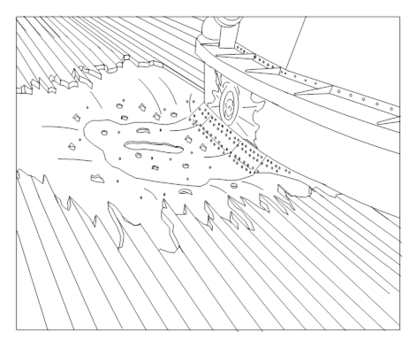
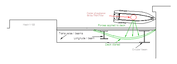
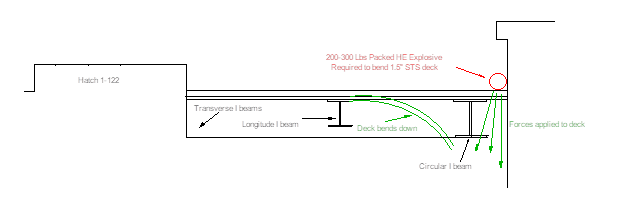
A Type 0 HE projectile is 4 feet long which places the center of the explosive force two feet away from the barbette surface. If the shell struck the upper impact scar 17 inches from the top of the barbette, then it would produce an open air explosion over the deck which would have caused the deck to dish. There would be no wood overhanging where the steel is bent down and the 64-pound TNA filler is not powerful enough to produce a 10 to 12 foot long hole in the 1.5-inch STS steel deck. The shell body of a HE projectile will never reach the barbette because when the fuze is crushed the shell will destroy itself almost instantaneously.
For the deck to get bent down and the hole to be directly up against the barbette surface due to an explosive force, the center of the charge must be placed directly up against the barbette and on the deck. The charge weight to produce such a large hole between 10 and 12 feet long in the 1.5-inch STS steel would need to be in the order of 200-300 lbs. of HE explosive. This size burster is impossible for a Japanese 14-inch Type 0 projectile.
We can compare Hit 11, which was made by a 14-inch Type 0 projectile striking on a 1.25-inch STS plate, and the deck area for Hit 26 to show how the damaged plates differ.
| Hit 11 | Hit 26 |
|---|---|
| Big, irregular hole blown in 1.25-inch STS plate right at the impact point. | No holes made in 1.5-inch STS plate whatsoever; just torn-out rivets. |
| Radiating cracks (especially one long horizontal crack due to a defect in the plate hit) and a shallow dish around the blast point. | No cracks and no dish; just a deeply curled down deck edge directly in front of the shell nose, bending down the edge to either side somewhat, too. Note that there is NO denting/dishing of the deck at all behind or directly to the sides the impact point in a circa-200-degree-wide arc centered on the hypothetical HE projectile's rear, which is impossible if a horizontal shell explosion were to blame, as most of the explosion effect of a HE shell is sideways from the center of the shell, where the main explosive charge is, not forward, where the narrow pointed nose is, so the deepest dent in the deck should be sideways (directly down and in an arc to either side), not in front of the shell, if a nearly horizontal HE shell caused the damage. |
| Many small pits and partial/complete middle-body fragment holes closely surrounding the central big hole. | Again, no holes made other than the existing rivet holes. |
| Center of damage is at shell impact point, radiating more-or-less in all directions, damaging the impacted plate the most right in the center where the blast was strongest. | Center of damage to the deck is the curled-down deck edge in front of a HE shell's narrow nose, well away from the main blast center of the shell, which is the lower and middle body, even though the deck about 3 feet away from the barbette would be directly under this center of the explosion if it was caused by a nearly horizontal HE shell detonating a few inches above that deck upon hitting the barbette. There is no evidence whatsoever of such a close-to-the-deck detonation, which would have left some kind of huge mark on the deck top surface, even if somehow no holes were made – an explosion sure made a distinct mark on the much more solid barbette face just above the deck! |
| Chunks of HE projectile and armor tore holes in the next thin HTS bulkhead inboard, being stopped by the main recessed Class "A" belt armor. Thus, the explosion and its fragments were powerful enough to tear through thin high-tensile steel plate even after punching through 1.25 inches of STS plate. | There were unsupported undamaged wood planks of the over-deck with only broken tips overhanging the bent-down deck region. A HE explosion that could tear holes in steel plate behind an STS armor plate, as in Hit #11, and which could also bend down 1.5-inch STS over a 10-12-foot-wide arc to a depth of 3 to 4 feet (this is typical World War II Tank Armor thickness, remember!), would have torn up the wood over-deck at a much farther distance than the distance it could bend armor steel plate. There could not possibly be overhanging wood planks in such a case. |
These inconsistencies show that the damage was not caused by a HE projectile detonating horizontal to the deck and that BuShip's original analysis was incorrect. Another consideration that also enters into this analysis is the fact that a Japanese nose-fuzed HE projectile simply does not have the capability of gouging a 1.5-inch deep gash in the face-hardened armor plate of the barbette. In other words, Japanese HE projectiles could not penetrate any thick, rigid Class "A" plate more than a slight flaking of the cemented surface layer caused by the burster exploding at point-blank range. There would be no deep conical pit in the armor as is the case for this hit. This alone can eliminate the HE shell type from consideration. Also, the only projectile type that could produce a Moiré (interference) Pattern due to reflected impact shock waves bouncing off the plate's rear surface, back into the brittle face layer, is from an AP projectile.
The fragment size and distribution also needs to be considered. A HE projectile, due to its larger shell cavity and thinner sides, breaks up into hundreds of small fragments with only a few large pieces coming from the base section. The actual projectile in this case produced many large fragments that passed through the scullery and through bulkhead 136. The fragment pattern for Hit 26 is typical of AP ammunition and inconsistent with HE ammunition.
Although not conclusive, the fact that this hit was from one of the last shots fired by Kirishima at a known battleship target would tend to make one surmise that the Japanese gunners had by now used up the Type 3 AA and Type 0 HE rounds already in the guns and hoists at the start of the battle and were by now firing AP rounds at this end stage of the battle.
When everything listed above is considered for Hit 26, the only projectile that fits all of the available evidence is the 14-inch Type 1 AP shell. This hit represents the only time in US Naval History that a US battleship was struck by a foreign battleship's main-caliber AP projectile and in this case South Dakota and her designers won the age-old contest between shell and armor. 79
38. The SC-1 radar antenna and mount were shot away and the radar platform was riddled with holes. From the appearance of Photo 39 it is probable that the radar was hit by a projectile that detonated on contact.
For this damage it is not clear if it was caused by fragments or a direct hit. In BuShips report Plate 1 it is listed as fragment damage but the BuShips' caption on the photograph in Figure 120 implies a direct hit. If so, a 5-inch nose fuze, Type 0 HE projectile is the most likely due to the relatively small area of the platform destroyed and it appears the shell detonated on impact. There are not many shell impacts close to the platform that actually detonated, so it seems unlikely that this damage was from fragments. Most of the shells that struck near Sky Control passed through the superstructure without detonating (Refer to Hits 9 and 12).
Some of the damage suffered by South Dakota does not appear to have been caused from shell hits. We believe that the likely cause is from near hits that sprayed the ship with shrapnel and caused concussive damage to the hull.
FLOODED TANKS
The following tanks were flooded.
A-11F, A-21F, A-23F, A-33F, A-39V, B-23F, B-31F, B-39F, B-71F, B-75V, B-77F, and B-79F
DIVERS REPORT
Starboard side
Six foot down seam opened up from frame 46 to frame 58.
Fifteen foot down seam opened up from frame 43 to frame 58.
Twenty-five foot down seam opened up from frame 52 to frame 93. Slight leaks between frame 93 and 117. Seam opened up about 2 feet in length at frame 118.
Bad opening in seam on bottom at frame 56. 80
It should be noted that South Dakota had suffered hull damage on 6 September 1942 when she ran aground on an uncharted reef in Lahai Passage, Tonga Islands. The battleship put into Tongatabu for emergency repairs by the repair ship Vestal (AR-4). Vestal's divers and repairmen, together with men from the battleship's crew, managed to mend the damage sufficiently by 8 September to allow the ship to return to Pearl Harbor for permanent repairs. The authors of this essay believe that this damage was fully repaired and is not related to the broken seams and flooded tanks suffered during the Guadalcanal Battle. 81
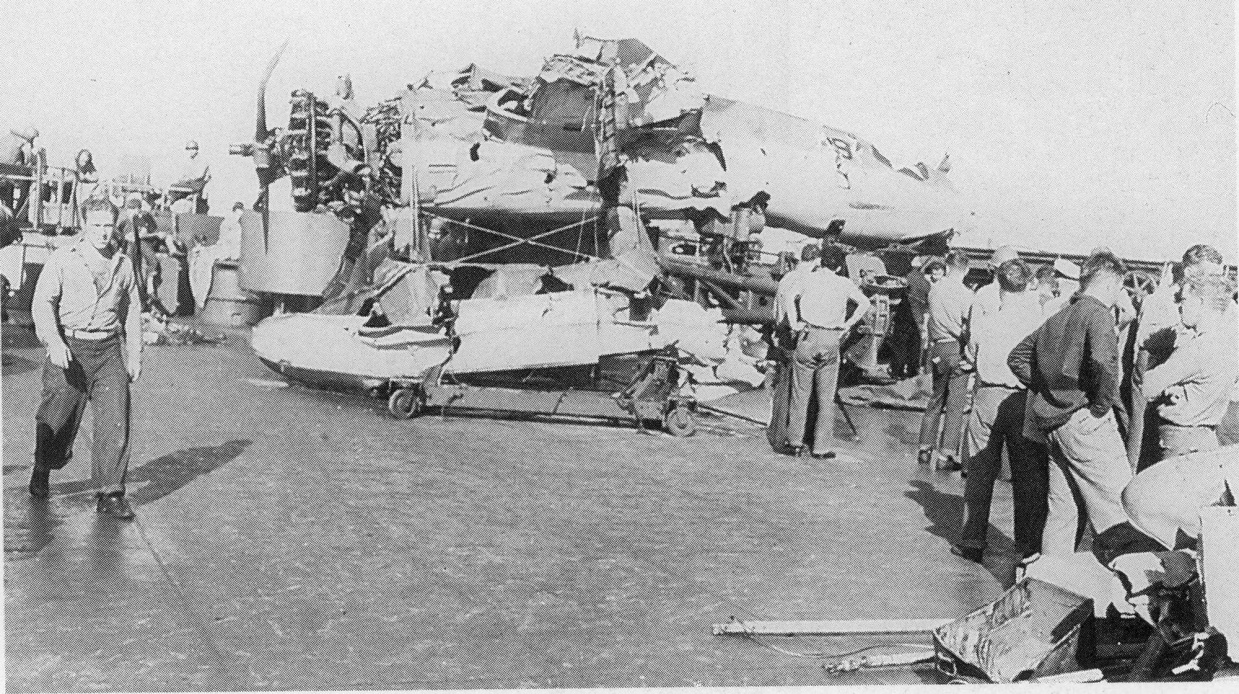
All three OS2U Kingfisher float planes were destroyed by South Dakota's own gunfire with two blown overboard during the battle. South Dakota's action report lists the following damage:
All planes destroyed. Two plane handling trucks were destroyed. 75
The projectiles that caused each Hit as estimated in this essay:
| Hit | Projectile |
|---|---|
| 1 | 6-inch Type 0 HE or Type 4 base-fuzed Common projectile |
| 2 | 14-inch Type 0 HE projectile |
| 3 | 6-inch Type 0 HE or 5.5-inch Type 2 HE projectile |
| 4 | 8-inch Type 91 AP projectile |
| 5 | 8-inch Type 0 HE projectile |
| 6 | 8-inch Type 91 AP projectile |
| 7 | 5.5-inch base-fuzed Common projectile |
| 8 | 5.5-inch base-fuzed Common projectile |
| 9 | 8-inch Type 91 AP projectile |
| 10 | 8-inch Type 91 AP projectile |
| 11 | 14-inch Type 0 HE projectile |
| 12 | 5.5-inch base-fuzed Common projectile |
| 13 | 6-inch Type 4 base-fuzed Common projectile |
| 14 | 6-inch Type 4 base-fuzed Common projectile |
| 15 | 14-inch Type 3 Incendiary AA projectile |
| 16 | 6-inch Type 4 base-fuzed Common projectile |
| 17 | 8-inch Type 91 AP projectile |
| 18 | 6-inch Type 4 base-fuzed Common projectile |
| 19 | 5.5-inch base-fuzed Common projectile or 6-inch Type 4 Common projectile |
| 20 | 6-inch Type 4 base fuze Common projectile |
| 21 | 14-inch Type 1 AP cap head and windscreen |
| 22 | 5-inch Type 0 HE projectile |
| 23 | 14-inch Type 3 Incendiary AA projectile |
| 24 | 6-inch Type 0 HE projectile |
| 25 | 8-inch Type 91 AP projectile |
| 26 | 14-inch Type 1 AP projectile |
| 27 | 5-inch Type 0 HE projectile or fragment damage |
Both the BuShips' report and the South Dakota's action report mention that many Japanese shells failed to properly detonate and thus the ship escaped more serious damage.
In reviewing all of the hits described in this essay, the authors found that the following ones did not have high-order detonations: Hits 1, 6, 8, 9, 10, 12, 13, 14, 15, 17, 19, 21 and 23.
Of these, Hits 15 and 23 were by 14-inch Type 3 Incendiary AA projectiles that broke apart and should not really be considered as duds. Hit 21 was made only by a cap head, so no explosive filler was involved and thus no possible detonation. Hits 1, 8, 9 and 19 were most likely from base-fuzed projectiles that did not hit anything thick enough or with significant mass to slow the projectile down or even activate the fuze.
Hit 6 and 10 were by 8-inch AP shells where their long fuze delay prevented detonation while they were still within the ship's structure. This sort of lack-luster performance was quite common in other actions where the Japanese used AP projectiles with long fuze delays.
Hits 12, 13 and 14 were from 5.5-inch and 6-inch shells that were duds, possibly due to mercury fulminate decay in storage as reported by the post-war US Naval Technical Mission. 9
Hits 4 and 25 produced low-order detonations. These both struck the main belt and probably both suffered from shatter, which may be the reason why they did not explode properly.
The one hit that failed to detonate that is hardest to explain is Hit 17, which was the 8-inch shell that the crew found on deck after the battle. This shell should have detonated given what it hit as it passed through the ship. In reviewing this hit, the authors have re-examined Japanese methodology for testing their shells and fuzes. It would appear that the very long (0.4-second) delay elements in Japanese Type 91/1 AP projectiles were not resistant to being slammed around sideways due to high projectile yaw, since the shells were only tested at 20 degrees obliquity against single 2/3rds-caliber thick face-hardened plate for their larger caliber shells, and against roughly the same thickness of homogeneous armor for their 6.1-inch and 8-inch caliber shells. In the case of the 6.1-inch and 8-inch Type 91 AP shells, the Japanese also tested them for hits up to 45 degrees obliquity, but only against rather thin, single homogeneous armor plates. This means that they did not think to test their designs for multiple impacts against thin plates. If you do not test for something, then you can be fairly sure that if that something happens that there is probably going to be a high chance of failure – in this case the brittle black powder pellet being subject to high sideways shock forces again and again in quick succession from all sides as the highly yawed shell hits several plates one after the other at different sideways angles (up-down, left-right, tilted in-between as the shell nose nutates) during the time that the pellet is burning down. This is one possible reason that the 8-inch Type 91 AP shell fuze in Hit 17 did not go off. The other possible reason is that the plates that the shell struck were just not thick enough to set off the fuze and by the time the shell hit the plate on the back of the port-side 5-inch twin gun mount, which was thick enough, the projectile was moving so slowly that even that impact shock was too weak to activate the fuze. This might especially be the case as the shell was so highly yawed that the impact force on the firing pin was not down the shell's centerline but as much sideways as lengthwise, thus jamming the firing pin (like those US torpedo firing pins that didn't work right).
This may be true for other dud shells 8-inches and up, as some of these hits on South Dakota were against plate too thin to reliably set off the base fuze and the black powder delay was perhaps not always reliable when knocked around by more than one plate hit (even thin plates) while burning.
The US Mark 21 base fuze used the primer explosion to jam the entire mechanism into a locked position during the rest of the 0.033-second delay, due to these heavy forces during oblique impact, but this would also work against hitting spaced plates. This was almost certainly due to failures with previous base fuzes when tested under more realistic conditions (higher obliquity, thicker plates, and/or multiple impacts during the delay time).
The following hits did detonate: Hits 2, 3, 4, 5, 7, 11, 16, 18, 20, 22, 24, 25, 26, and 27. Of these, the following were definitely high order detonations: Hits 2, 3, 5, 7, 11, 16, 18, 20, 22, 24, 26 and 27. However, only Hits 2, 5, 11 and 26 were by large-caliber shells. All of the rest were from 6-inch or smaller-caliber projectiles. Hits 2, 5 and 26 are very noticeable as having struck above deck or very close to the main deck. Hit 11, being close to waterline, was probably not as noticeable. When the BuShips' report notes that they found three high order detonation hits, we would believe that they counted Hits 2, 5 and 26. These are also the ones that produced the largest holes in the ship.
The story of South Dakota's battle damage developed like a murder mystery as we found new information on just how the battle actually happened. As we stitched together more information concerning Kirishima and discovered that she had opened fire long before the heavy cruisers and that Japanese records show that she had hit on her first salvo in South Dakota's superstructure, with multiple men all observing the same event from various ships, I started to wonder what they actually saw and could it be true.
For example, Admiral Lee saw South Dakota being hit and sent messages asking her if she was OK at 0049, which was one minute after the Japanese light cruisers opened fire. He witnessed her veering south at 0054, so he was fully aware that she was taking fire long before Washington opened fire at 0100. This is important in that it tells us that the times listed in South Dakota's report are accurate. But, if these are accurate, then a question formed as to how the BuShips report in 1947 could be accurate in stating that her Radar Plot was ripped by 8-inch shells as that damage was inflicted at a time before any 8-inch shells were ever fired. Having found this discrepancy, then the next question was; were there other inaccuracies in the BuShips report? The more I rummaged through this report, the ship's own concurrent damage reports and the Japanese reports, the more it seemed that the conclusions in the BuShips' report could no longer be taken for granted. I found that I needed to gather up all the clues and put them in some sort of order so that a new analysis of South Dakota's damage could be created.
My major contribution for this essay was in finding this new information and finding the inconsistencies among the various documents. However, it is Nathan Okun who provided the expertise to determine the type of shells that may have caused the damage. As Nathan works for NAVSEA (though this historical study is not related to his job there), which at one time was BuShips, it is fitting that he participate in this re-examination of South Dakota's battle damage.
The physical evaluation of her damage as described in this essay now confirms what the Japanese witnessed and reported this night. Documentation from both United States and Japanese sources can now be seen to support each other so that when placed together this battle can now be placed into context as it has never been done before.
Overall, the South Dakota class battleships were tough ships. Their internal armor arrangement meant that Japanese AP shells faced a complex set of defenses that would typically remove their nose ballistic and AP caps before they struck the armor plates. The side shell of these ships was strong enough to limit the damage of even the largest Japanese HE caliber shells fired at point blank range. At Guadalcanal, the "All-or-Nothing" armor system worked as her designers intended in limiting structural damage and keeping the ship's fighting capacities intact.
USS South Dakota was hit by 26 or possibly 27 shells when we add the shell making a direct hit on the Radar platform (Hit 27). Between the cruisers, destroyers and Kirishima's secondary battery, the Japanese hit an estimated 13 to 14 times with 5-inch to 6-inch shells. The heavy cruisers Atago and Takao between them contributed at least seven 8-inch shell hits. Kirishima added another six hits from her main battery. Considering that Kirishima may have suffered as many as twenty 16-inch hits in a five to seven minute time span, 82 losing 50% of her main battery from gunfire and associated destruction, she did well to score this many hits. However, the performance of South Dakota's armor shows just how well she was designed and built to survive damage even when involved in a night fight at point blank range.
In a larger context, the importance of this battle should not be underestimated in any study of US Naval History. Japan chose war instead of a diplomatic solution primarily based upon the belief that her military forces could decisively defeat the US Navy in a short, limited war. The Japanese believed that this defeat would shock the US public into accepting the Japanese gains from this war and that they would not want to face an extended campaign to win back captured territories. The Japanese Government knew prior to hostilities that a long war with the US and its vast industrial power could not be won and they understood that it was imperative that Japan win quickly before the US industrial capacity could take effect. Unfortunately, when the time came to finish the US fleet in November 1942, Admiral Yamamoto failed to understand just how limited were the US resources at that moment. His November offensive was poorly planned and failed to take advantage of the Japanese superior numbers in ships at a time when his US counterpart Admiral Halsey was committing his last three capital ships (USS Enterprise, USS Washington and USS South Dakota to battle in order to hold Guadalcanal. 83 After the battles of 12 to 15 November 1942 where the battleships Hiei and Kirishima were sunk, Admiral Yamamoto lost his will to continue the struggle for Guadalcanal and withdrew the Combined Fleet far back in preparation for a long war that he already knew was impossible to win. The November Naval Battles around Guadalcanal decisively changed the course of the Pacific War in favor of the US and thus decided the fate of Japan.
During the Battle of Santa Cruz on 26 October 1942, USS South Dakota valiantly attempted to protect the USS Enterprise from Japanese aircraft attacking the carrier.
Figure 125 84 demonstrates the massive AA gunfire put out by the various US ships at this battle. USS South Dakota can be seen in the background firing her starboard secondary battery (white flash amidships) in her attempt to protect USS Enterprise. Officially, South Dakota was credited with shooting down 26 planes in this action.
During this battle South Dakota was hit by a single 500 lb. HE bomb on the starboard side of Turret I – the main battery turret closest to the bow. Fragments from this bomb struck Captain Gatch, who was on the bridge wing. The fragments hit his neck and jugular vein and almost killed him. Quick action by those around him saved his life. Forty-nine other men were wounded by the blast and one later died of his wounds. The damage to the ship resulted in minor damage to the roof plates of turret one, gouging of all three gun barrels of Turret II, along with various fragment damage to the forward superstructure. The most serious damage was the gouging of the left and center guns of Turret II. These guns were so severely gouged that they could not be used in the November battles, reducing her to seven 16"/45 main battery guns instead of the normal nine.
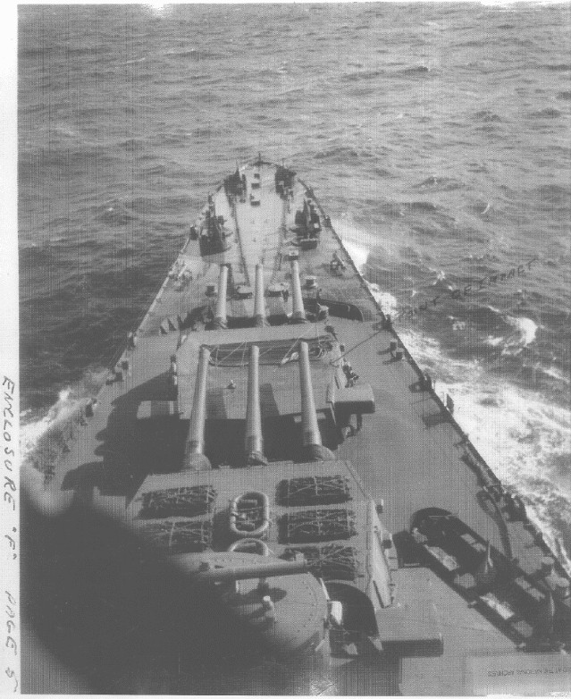
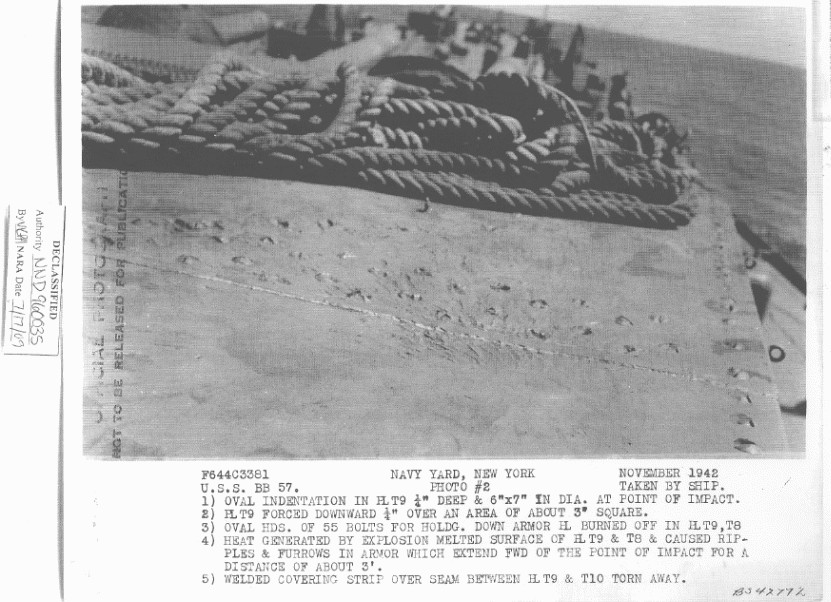
Figure 126 shows the location of the bomb hit to Turret I.
Figure 127 above shows a close up of the impact site and illustrates the negligible damage the bomb caused to the roof plate itself.
Damage within the gun house due to shock is seen in the next three photographs, showing seam and weld damage.
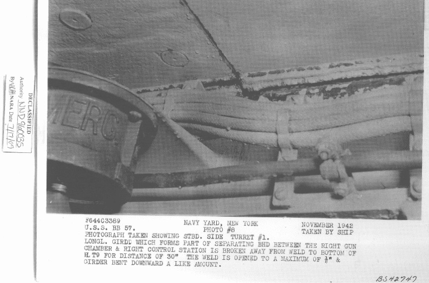
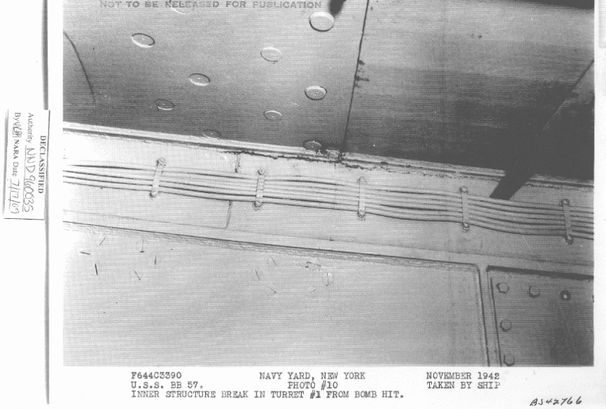
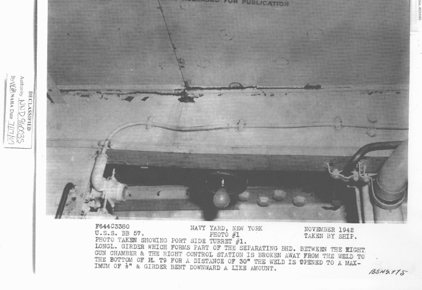
All three guns of turret two were gouged to some extent. The next two photographs show the damage to one of the gun barrels.
A few days after the Santa Cruz Battle, at 0414 on 30 October, while avoiding a submarine contact, South Dakota and the destroyer USS Mahan (DD-364) collided, causing damage to both ships. Mahan's bow was turned to port and crumpled to Frame 14, and a fire, soon brought under control, started in her forward hold. Both ships continued to Noumea where repair ships Prometheus (AR-3) and Vestal (AR-4) repaired South Dakota's and Mahan's damage. 85
Figure 133 shows USS South Dakota (BB-57) being repaired by USS Prometheus (AR-3), probably at Noumea, New Caledonia, in November 1942. The inboard destroyer, with the distorted bow, is probably USS Mahan (DD-364). The other destroyer may be USS Lamson (DD-367). 86
- ^Nathan Okun is a computer and weapons specialist who has years of research into World War II naval gunfire and ballistics. He developed the computer program FACEHARD which accurately reflects World War II shell damage on face hardened armor. His formulas and knowledge were extensively used for this essay and without his help this essay would have been impossible.
- ^BuShips War Damage Report # 57, page 3
- ^Interrogation Nav No. 33, USSBS No. 138
- ^Shell and fuze data in this table is primarily from the U.S. Naval Technical Mission to Japan Report O-19 Japanese Projectiles General Types. It should be noted that the Japanese Navy adopted metric units for their guns and projectiles in 1917 but that English units will be used throughout this essay in order to avoid confusion with the BuShips and South Dakota reports which used English units for these shells. The number of 14-inch rounds fired is from the testimony of LCDR Ikeda as described in Shikikan-tachi no Taiheiyō Sensō [The Pacific War as Described by the Senior Officers]. The number of 8-inch rounds fired is from figures given in Atago Direct Action Report and Takao Brief Action Report JT 1. This total includes some 8-inch rounds that Atago fired at Washington during the battle. Atago Direct Action Report also provides the number of 5-inch rounds that she fired during the battle.
- ^TNA = Japanese Tri-Nitro-Aniso, designated as Type 91 bakuyaku (Model 1931 Explosive). This was a more stable burster than the picric acid (Shimose) used in older Japanese projectiles. Both picric acid and TNA were about 10% more powerful but less stable than the Explosive D used as the burster in USN projectiles.
- ^A total of 49 5-inch rounds were fired by Atago during the battle.
- ^U.S. Naval Technical Mission to Japan Report O-17 Japanese Projectile Fuzes and Kaigun Hōjutsu-shi [The History of Naval Gunnery]
- ^The data in this table is primarily from U.S. Naval Technical Mission to Japan Report O-17 Japanese projectile Fuzes
- ^These drawings are based upon sketches in the two-volume book BuOrd OP 1667, Japanese Explosive Ordnance
- ^USS South Dakota Action Report, Enclosure D, pages 8 and 9
- ^Atago Direct Action Report and Shikikan-tachi no Taiheiyō Sensō [The Pacific War as Described by the Senior Officers]
- ^US Class "B" armor, STS and HTS are all "homogeneous" types, that is, they have a uniform quality throughout their thicknesses. By contrast, US Class "A" armor is Face Hardened.
- ^For Nathan Okun's equations to work correctly; projectiles with 6.0 to 8.99% filler percentages are considered to be normal World War II HE shells; projectiles with fillers of 4.0 to 5.99% are considered to be normal World War II SAP shells; and rounds with fillers of 1.4 to 2.99% are considered to be normal World War II AP shells. This will be further developed later in this essay. Bombs have fillers of 9.0% and larger and these use a different equation that Nathan is in the process of developing.
- ^It should be understood that Equations of this type were not available to BuShips in 1947 and could only be developed by using modern, high-speed computing methods.
- ^The range from Kirishima, Takao and Atago to South Dakota is estimated to have been as far as 7,500 yards to as close as 4,700 yards during the time of 0100-0106 when the Japanese ships were firing during this phase. As the exact time of impact for most hits is unknown, we have used an average range of 6,000 yards and the associated striking velocities for this range in the damage calculations for the 8-inch and 14-inch projectiles that are judged to have hit during this time.
- ^Sectional density of this projectile would be (W/D3) = 1,378 / 2,744 = 0.5.
- ^Nathan Okun also uses this same multiplier for the contact-hit, all-distances-under-5-calibers 0.156-caliber-STS-plate-thickness-for-a-caliber-wide-hole HE shell computation too, since filler blast punching power is what is changing, not the fragments, as filler size steps down to the SAP range and then to the AP range (thus, 0.156 becomes 0.135 for an SAP round, and 0.113 for an AP round).
- ^For an AP projectile that uses a 1.4 to 2.99% filler charge, the caliber wide hole at a distance of 5-calibers is reduced to 0.08 calibers thick STS plate. The ratio would then be 0.08 / 0.11 = 0.727 for an AP projectile.
- ^For a simple first approximation, Nathan Okun uses this 0.864 multiplier for ALL hole size computations for SAP rounds.
- ^Michio Kobayashi in "Senkan ‘Kirishima' no Saigo" [The Last of Battleship Kirishima]
- ^USS South Dakota Action Report, Enclosure D, page 8
- ^USS South Dakota Action Report, Enclosure D, page 13
- ^This may be a good place to note that Atago's Direct Action Report claims no hits on South Dakota and gives credit to Takao and Kirishima for all of the damage inflicted on South Dakota.
- ^USS South Dakota Action Report, Enclosure D, page 5
- ^USS South Dakota Action Report, Enclosure D, pages 5 and 6
- ^Japanese Technical Mission Report 0-19 Japanese Projectiles General Types
- ^Atago Direct Action Report and Takao Brief Action Report JT1, although this report also says that she did not hit South Dakota during the battle.
- ^USS South Dakota Action Report, page 8
- ^USS South Dakota Action Report, page 8 and Takao Brief Action Report JT1
- ^USS South Dakota Action Report, page 14
- ^USS South Dakota Action Report, Enclosure D, page 8. This particular Director must have been a source of annoyance to the ship's crew. In the "Gunnery Damage" section on page 15 of Enclosure D, there is the following entry: "Mark 45 director received direct hit through center of director. (Three cheers)"
- ^WRSR or W.R.S.R. = Wardroom Stateroom, i.e., officers' quarters
- ^USS South Dakota Action Report, Enclosure D, pages 6 and 7
- ^BuShips War Damage Report # 57, pages 7and 8
- ^USS South Dakota Action Report, Enclosure D, pages 7 and 8
- ^USS Washington Action Report, page 10
- ^Admiral Kondo as quoted in The Pacific War Papers: Japanese Documents of World War II and LCDR Ikeda as quoted in Shikikan-tachi no Taiheiyō Sensō [The Pacific War as Described by the Senior Officers]
- ^USS South Dakota Action Report, page 8 [Ed's note: This paragraph seems to be conflating Hit 24, which glanced off Mount #5 but did not penetrate into the superstructure, together with Hit 17 which did not hit any of the starboard side 5-inch twin mountings but which did pass through the superstructure and struck the rear of Mount #2. According to both the BuShips report and the "Gunnery Damage" section of Enclosure D, Mount #4 did not suffer any damage at all in this battle.]
- ^MWB = Motor Whale Boat
- ^USS South Dakota Action Report, Enclosure D, pages 3-5
- ^The heavy cruisers only scored hits between 0102 and 0106 and during this time their range to South Dakota was between 5,600 yards and 4,700 yards. For Type 88, Type 91, Type 1 and any other similar tapered, flat-nose shell-body design, only those striking calm water at angles over 7 degrees were able to reliably dive and avoid skipping. John Campbell in Naval Weapons of World War Two, page 186, states that the angle of fall for an 8-inch Type 91 AP projectile was 3.0 degrees at 5,470 yards (5,000 m). This implies that any 8-inch round that landed short of South Dakota during this phase of the battle had a high probability of skipping.
- ^Nutation – A "spiral", "corkscrew", or "helical" motion of the tip of the projectile nose as it moves forward such that the yaw angle is tilting in different directions as the projectile moves forward – like the tip of a propeller on a fast-moving ship.
- ^As shown in Figure 59, this shell made a huge gouge into the side of the safe, knocked off the left-side door, snapped open the right-side door, and partially pulled the safe from its heavily-reinforced foundation, tossing the left door and the safe's contents all over the room. This safe was made of metal similar to homogeneous armor steel, so its effect on the projectile's motion thereafter was considerable.
- ^Track Chart from The Battleship Action 14-15 November 1942 and is based upon the track charts given in Enclosure A of USS Washington's Action Report
- ^USS South Dakota Action Report, Enclosure D, page 16
- ^USS South Dakota Action Report, Enclosure D, page 13
- ^USS South Dakota Action Report, Enclosure D, page 7
- ^USS South Dakota Action Report, pages 15 and 16
- ^USS South Dakota Action Report, Enclosure D, pages 9 and 10
- ^USS South Dakota Action Report, Enclosure D, page 10
- ^USS South Dakota Action Report, page 3
- ^USS South Dakota Action Report, page 8. These parting shots may have been from Atago, which had switched fire back to South Dakota around this time after shooting at Washington. Atago Direct Action Report.
- ^USS South Dakota Action Report, page 11. It should be noted here that Kirishima was not the lead ship in the Japanese formation nor was any of her damage inflicted by South Dakota. Atago, which was the lead Japanese ship in the formation and which had been struck by gunfire from South Dakota, was not seriously damaged in this battle.
- ^USS South Dakota Action Report, Enclosure D, page 12
- ^USS South Dakota Action Report, Enclosure D, page 19
- ^All ballistic calculations were done with MS QuickBasic 4.5 computer EXTERIOR BALLISTICS 6G1109. 100 fps were removed from new gun velocity to mimic extreme wear on liners (worst case scenario). Type 1 AP data with adjusted Form Factor of 1.0864. Kirishima started the battle with reduced charges purposely to avoid more wear on the liners so she could stay at the front lines longer before she was forced to go back to Japan to get them re-lined.
- ^All drawings were done to scale based on official copies of South Dakota's blueprints and direct measurements taken aboard USS Alabama on 16 January 2010.
- ^Japanese 14-inch and 16.1-inch projectiles were proof tested to 20 degree impact angles and the 18.1-inch were proof tested to 30 degree impact angles against plates only about 2/3rds of the projectile's diameter of Vickers Cemented (VC) face-hardened belt armor made before World War I – circa 9-inch plate for the 14-inch shells, 11-inch plate for the 16.1-inch shell, and 12-inch plate for the 18.1-inch shell. The 18.1-inch shell was not significantly better than the smaller rounds against proportionately thicker plate or at higher obliquity.
- ^For an earlier work by Nathan Okun on Hit 26, please see his essay on the subject at the NavWeaps Naval Technical Board.
- ^USS South Dakota Action Report, Enclosure D, page 13
- ^USS South Dakota DANFS entry, USS Vestal DANFS entry
- ^The Naval Battles of Guadalcanal took place from 11 November through to 15 November 1942. USS Enterprise (CV-6) played a pivotal role in sinking Kirishima's sister ship Hiei, as well as 7 of the 11 troop transports bringing in Japanese reinforcements, on the days leading up to the final night battle carried out by USS Washington and USS South Dakota. When the Naval Battle of Guadalcanal began, both Enterprise and South Dakota still carried battle damage suffered on 26 October 1942 during the Naval Battle of Santa Cruz. The tactical situation at Guadalcanal was considered to be so critical that neither ship could be sent out of the war zone for repairs.
- ^Official U.S. Navy Photograph USNHC # 80-G-20989, from the collections of the Naval Historical Center
- ^USS South Dakota DANFS entry, USS Mahan DANFS entry, USS Prometheus DANFS entry, USS Vestal DANFS entry
- ^Official U.S. Navy Photograph USNHC # 36088, from the collections of the Naval Historical Center
Bureau of Ordnance (BuOrd)
– OP 1667, Japanese Explosive Ordnance
Bureau of Ships (BuShips)
– War Damage Report No. 57, 1 June 1947. U.S.S. SOUTH DAKOTA (BB57), Gunfire Damage, Battle of Guadalcanal, 14-15 November 1942
– Builder plans for USS South Dakota
Reports of the U.S. Naval Technical Mission to Japan
– O-17 Japanese Naval Projectile Fuzes
– O-19 Japanese Projectiles General Types
– O-25 Japanese Explosives
– O-47(N1) Japanese Naval Guns and Mounts, Article 1 - Mounts under 18”
– O-54(N) Japanese Naval Guns
Japanese Action Reports
– Atago Direct Action Report No. 8, 12 to 14 November 1942 (submitted 18 November 1942)
– Ikazuchi Direct Action Report, 14 to 15 November 1942 (submitted 15 November 1942)
– Kirishima Brief Action Report JT 1, National Archives
– Sendai Brief Action Report JT 1, National Archives
– Takao Brief Action Report JT 1, National Archives
United States Action Reports and Deck Logs
– Admiral W.A. Lee. Report of Night Action Task Force 64 – Night of November 14-15, 1942
– USS South Dakota. Action Report, night engagement 14-15 November, 1942, with Japanese naval units, off Savo Island.
– USS Washington. Action Report, Night of November 14-15, 1942.
– USS Washington. Deck Logs – Night Action – 14-15 November 1942
United States Strategic Bombing Survey
– Interrogations of Japanese Officials, Interrogation Nav No. 33, USSBS No. 138, Interrogation of LCDR Tokuno Horishi
Campbell, John. Naval Weapons of World War Two. Conway Maritime Press, 1985.
Dull, Paul S. A Battle History of the Imperial Japanese Navy, 1941-1945. Naval Institute Press, 1978.
Evans, David C. and Mark R. Peattie. Kaigun: Strategies, Tactics and Technology in the Imperial Japanese Navy 1887-1941. Naval Institute Press, 1997.
Frank, Richard B. Guadalcanal. Penguin Books, 1990.
Garzke, William H. and Robert O. Dulin, Jr. Battleships: United States Battleships. Naval Institute Press, 1995.
Grace, James W. The Naval Battle of Guadalcanal: Night Action, 13 November 1942. Naval Institute Press, 1999.
Hammel, Eric. Guadalcanal: Decision at Sea. Crown Books, 1988.
Lacroix, Eric and Linton Wells II. Japanese Cruisers of the Pacific War. Naval Institute Press, 1997.
Skulski, Janusz. The Heavy Cruiser Takao. Naval Institute Press, 1994.
Handō, Kazutoshi (ed.). Nippon Gunkan Senki [Battle Records of Japanese Warships]. Bunshun Bijuaru-han, 1996.
Kaigun Hōjutsu-shi [The History of Naval Gunnery]. Kaigun Hōjutsu-shi Kankōkai, 1975.
Shikikan-tachi no Taiheiyō Sensō [Pacific War as Described by the Senior Officers]. Kōjinsha NF Bunko, 2004.
Toyoda, Jō. Kūbo Shinano no Shōgai Yonhon no Hibashira: Kōsoku Senkan Yūsenki [Four Pillars of Fire: The Battle Records of the Fast Battleships]. Shūeisha Bunko, 1979.
Yoshimura, Akira. Senshi no Shōgensha-tachi [Witnesses of the Pacific War]. Bunshun Bunko, 1999.
Gakken Pacific War Series:
– Vol. 5: Soromon Kaisen [The Solomons Campaign], 2000.
– Vol. 6: Shitō Gadarukanaru [Deadly Battle for Guadalcanal], 2000.
– Vol. 21: Kongō-gata Senkan [Kongō Class Battleships], 1999.
Lengerer, Hans. “The Kongō Class” Contributions to the History of Imperial Japanese Warships, No. 2, March 2007, pp 18-30; No. 3, Sep. 2007, pp 25-44.
Lundgren, Robert. The Battleship Action 14-15 November 1942
Okun, Nathan
– TABLE OF METALLURGICAL PROPERTIES OF NAVAL ARMOR & CONSTRUCTION MATERIALS
– MISCELLANEOUS NAVAL-ARMOR-RELATED FORMULAE
– Kirishima’s Hit on South Dakota
– Underwater Projectile Hits
Kobayashi, Michio. Senkan 'Kirishima' no Saigo [The Last of Battleship Kirishima].” Saiaku no Senjō Gadarukanaru Senki, 1987, pp 350-361.
Yoshino, Kyûshichi. Senkan 'Kirishima' no Saigo [The Last of Battleship Kirishima].” Maru Extra Vol. 10, May 1998, pp 54-57.
USS Alabama Memorial Park, Mobile, Alabama
Special Thanks to Bill Tunnel of USS Alabama for all his help
MS QuickBasic 4.5 computer program EXTERIOR BALLISTICS 6G1109
Special thanks to Sander Kingsepp for his help and expertise in translating Japanese documents.
This essay is copyrighted by Robert Lundgren, Nathan Okun and NavWeaps and may not be used for commercial purposes without prior written authorization.
This essay was originally written in 2009-2010 in Microsoft Word. It has since been updated a few times as described below and has now been converted to Microsoft Word 2019. It is this version that was converted to HTML 5 and appears here. This Word document was also converted to pdf format via Foxit PhantomPDF. This pdf is a much more readable document and the photographs and diagrams show up in better detail and crispness, but this file is too large for the internet. Please send me an Email by clicking on the Contact link below if you are interested in obtaining a copy of this document.
01 October 2010 - Benchmark
15 May 2015 - Corrected various typographical and Word problems, rescanned photographs for better resolution
11 December 2020 - Converted source document to Word 2019, added Self-Inflicted Damage, Other Damage and Appendix sections, converted to HTML 5 format
06 March 2021 - Fixed broken note link
15 May 2022 - Dropped PayPal link
21 August 2022 - Formatting cleanup
05 November 2023 - Fixed gallery formatting issues

