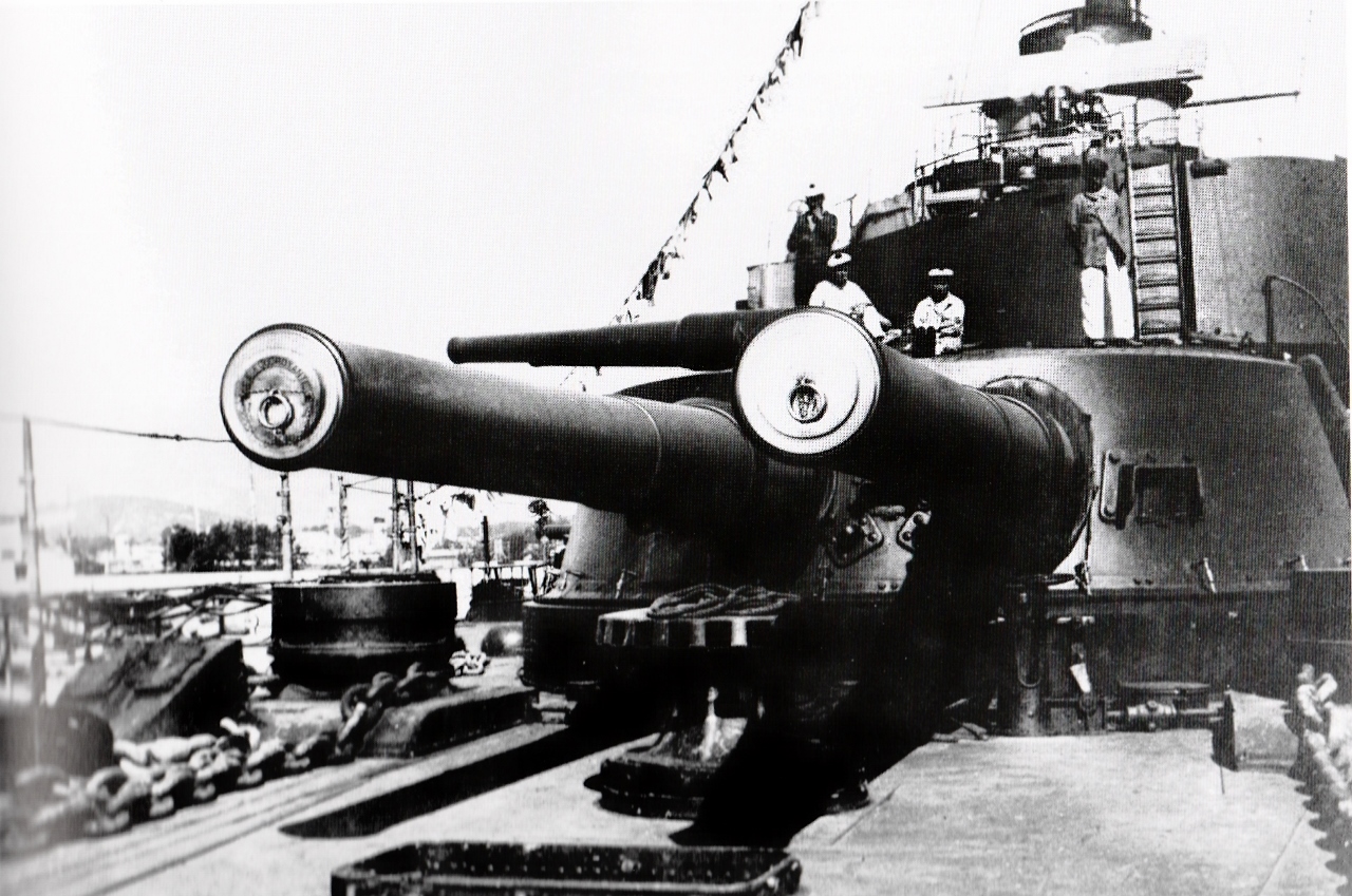
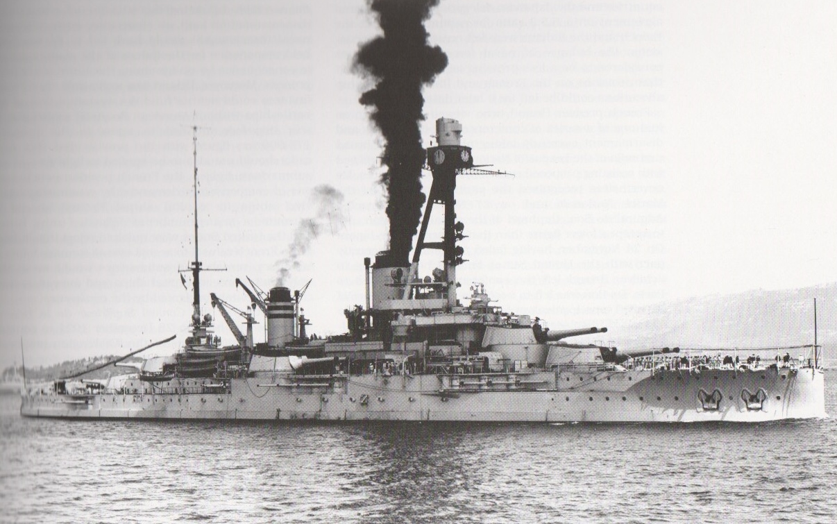
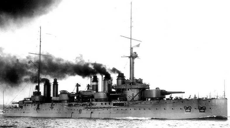
The French navy used the Model 1906 on the last of their pre-dreadnoughts and the Model 1906-1910 on the first of their dreadnought battleships. Both models are listed as being used as railway ordnance during World War I.
Construction was a complicated built-up design, similar to other French heavy guns. The two model types were similar, differing in minor constructional details. These 30 cm/45 guns were of lighter construction and had a stronger breech piece than the previous 305 mm/40 guns. Breech mechanism for the Model 1906 was Manz-type interrupted screw breech block while the Model 1906-1910 used an interrupted-thread breech block with a Farçot breech mechanism which could be operated electrically or manually.
A Note on Sources: Many references say that the 1906-1910 guns had Welin breech blocks, but I believe them to be incorrect. The later 34 cm Model 1912 guns still used interrupted thread breech blocks with a Farçot breech mechanism, so it would be likely that these earlier guns used the same design.
French guns designed between about 1902 and 1922 were designated in centimeters. Actual bore diameter was 30.5 cm (12.008").
| Designation | 30 cm/45 (12") Model 1906
30 cm/45 (12") Model 1906-1910 1 |
|---|---|
| Ship Class Used On | Model 1906: Danton class
Model 1906-1910: Courbet class |
| Date Of Design | 1906 & 1910 |
| Date In Service | Model 1906: 1911
Model 1906-1910: 1915 |
| Gun Weight | Both: 120,590 lbs. (54,700 kg) |
| Gun Length oa | 558.07 in (14.175 m) |
| Bore Length | Model 1906: 540.55 in (13.730 m)
Model 1906-1910: 536.42 in (13.625 m) |
| Rifling Length | N/A |
| Grooves | (90) 0.071 in deep x 0.118 in (1.8 mm deep x 3 mm) |
| Lands | N/A |
| Twist | Uniform RH 1 in 43 |
| Chamber Volume | 12,921 in3 (211.787 dm3) |
| Rate Of Fire | 2 rounds per minute 2 |
| Type | Bag |
|---|---|
| Projectile Types and Weights 1a 2a | Model 1906 Guns
APC Model 1906: 960 lbs. (435.5 kg) 3a 4a Model 1906-1910 Guns
Both Model 1906 and Model 1906-1910 Guns
Railway Projectiles
|
| Bursting Charge | APC Model 1906: 25.0 lbs. (11.32 kg) Melinite
APC Model 1910(?): 36.3 lbs. (16.46 kg) Melinite HE Model 1916: N/A German 30,5 cm Spgr. L/3,1 (Kz): 65.0 lbs. (29.5 kg)
|
| Projectile Length) 8a | APC Model 1906: 40.923 in (103.94 cm)
APC Model 1910(?): 40.923 in (103.94 cm) HE Model 1916: N/A German 30,5 cm Spgr. L/3,1 (Kz): 37.3 in (94.8 cm)
|
| Propellant Charge 9a | APC Model 1906: 320 lbs. (145.0 kg) BM17
APC Model 1910(?): 274 lbs. (124.3 kg) BM17 HE Model 1916: 280 lbs. (127 kg) BM15 10a Others: N/A |
| Muzzle Velocity | Model 1906 with APC Model 1906: 2,559 fps (780 mps)
Model 1906-1910 with APC Model 1910(?): 2,569 fps (783 mps) 11a Both Model 1906 and Model 1906-1910 with HE Model 1916: 2,789 fps (850 mps) Others: N/A |
| Working Pressure | Both: 16.5 tons/in2 (2,600 kg/cm2) |
| Approximate Barrel Life | 300 rounds |
| Ammunition stowage per gun | Danton: 81 rounds
Courbet: 100 rounds |
- ^A Note on Sources: The secondary sources listed below differ greatly on the details for the ammunition used for these guns. John Jordan kindly provided me with information taken from French official documents and these values are used throughout this section.
- ^Official Projectile Designations:
Actual French designations APC Model 1906 OPfK Mle 1906 APC Model 1910(?) OPfK Mle 1910(?) HE Model 1916 FAB Guerre Mle 1916 - ^Weights for the APC 1906 differ in official documents with a weight of 970 lbs. (440 kg) also being seen.
- ^4.14.2The APC projectiles for these guns were classified as obus alourdi (heavyweight shell). The base fuzes for these projectiles had a dual delay mechanism which in theory enabled them to engage both thin-skinned and heavily armored targets. They therefore replaced both the separate APC (obus de rupture) and SAPC (obus de semi-rupture) shells carried by earlier battleships. These dual delay base fuzes did not work particularly well but their performance was improved over the years.
- ^The actual Model year for this APC is not known. "1910" is John Jordan's best estimate based upon official French documents. Weights for the APC Model 1910(?) differ in official documents with a weight of 952 lbs. (432 kg) also being seen. The design of this projectile was apparently modified post-war to have flatter AP and ballistic caps, similar to the 34 cm APC M1912-1921. See sketch below. Similar to the 34 cm APC, these modified shells were then probably redesignated as 30.5 cm OPf Mle 1910-1921.
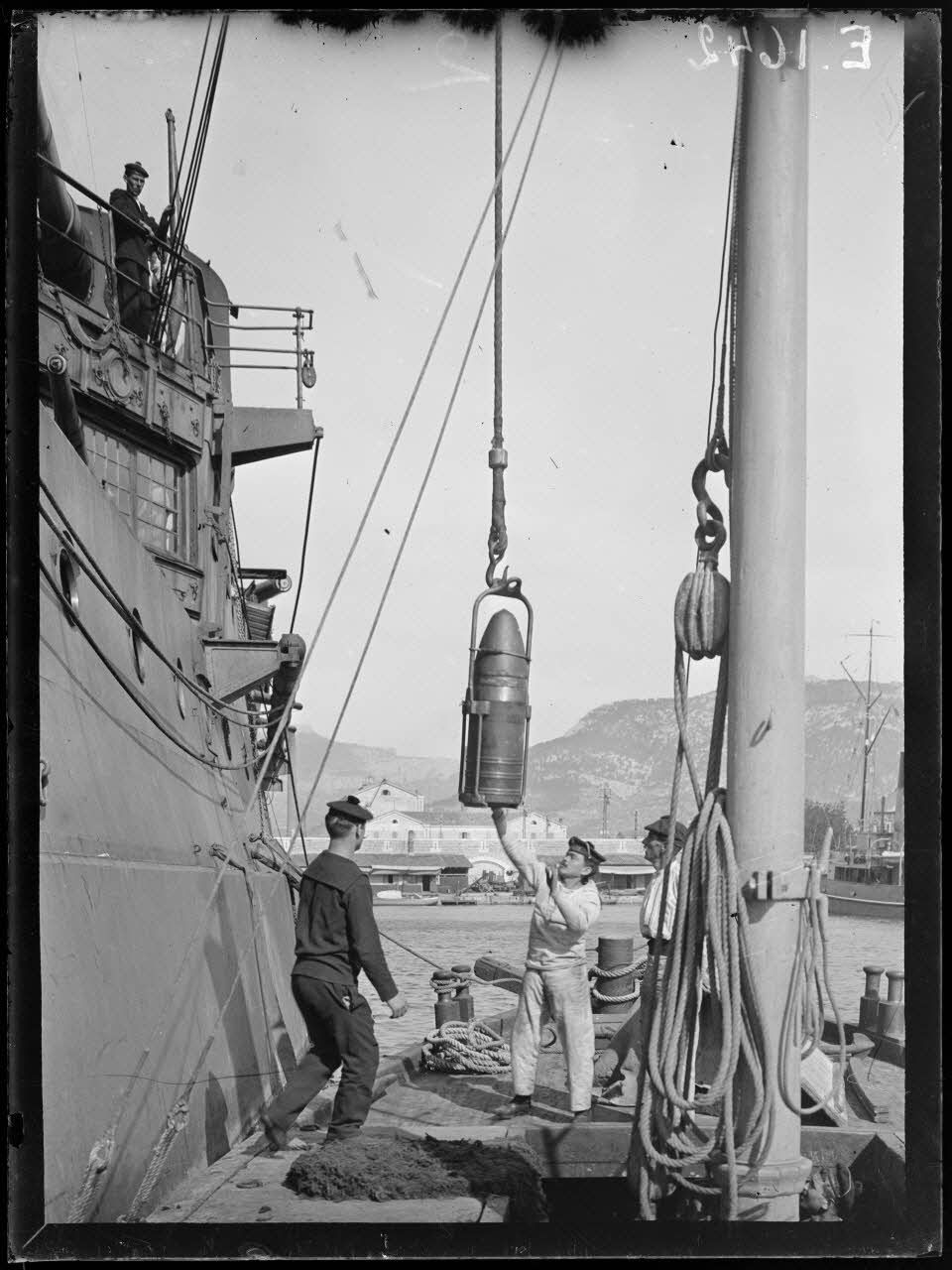
- ^As an attempt to increase the range of these guns against land targets, in 1917 the Navy adopted an HE shell that had been developed by the Army for use with its railway guns. The official designation of this shell was FAB Guerre Mle 1916. About 70 of these shells were carried by each ship.
- ^As these guns had a steep twist (1 in 43), the shells for them had relatively short bodies.
- ^Propellant charges were in quarters for both the Model 1906 and the Model 1906-1910 guns. A Note on Sources: "Naval Weapons of World War One" incorrectly says that the charges for the Model 1906 gun were in halves.
- ^The propellant load for the HE Model 1916 projectile was reduced from that for the APC Model 1906 as the HE projectile had thinner walls than did the APC Model 1906 projectile and could not handle the added stress of a full charge. This lower charge weight still gave the HE Model 1916 a much higher muzzle velocity and a longer range than either of the APC projectiles.
- ^Muzzle Velocity for the Model 1906-1910 gun using APC Model 1910(?) differs in official documents with an MV of 2,618 fps (798 mps) also being seen. These may be new gun vs. average gun differences.
- Projectiles had three driving bands.
- These projectiles were not given dye loads during the 1930s as they did not have a ballistic cap to accommodate them. This was probably because when the French Navy was implementing dye loads in the late 1930s, the two surviving (active) ships of the Courbet class were both being used as gunnery training ships and not as front-line units.
| Elevation | Range |
|---|---|
| 12 degrees | 15,860 yards (14,500 m) |
| Elevation | Range |
|---|---|
| 12 degrees | 14,760 yards (13,500 m) |
| 23 degrees | 22,530 yards (20,600 m) 1b |
- ^A Note on Sources: A range of 26,000 m (28,430 yards) for this elevation is found in both official and secondary sources. A ballistic study by William Jurens and José Medina published in Warship International states that a more realistic range would be 19,200 m (21,000 yards) at a muzzle velocity of 790 mps (2,590 fps). John Jordan believes that the 26,000 m figure was a mistype and that the actual value was probably 20,600 m (22,530 yards). I have chosen to use the latter value here.
| Elevation | Range |
|---|---|
| 12 degrees | 18,260 yards (16,700 m) |
| Angle of Incidence | Range | Harvey Armor |
|---|---|---|
| 0 degrees | 6,560 yards (6,000 m) | 15.35" (390 mm) |
| 0 degrees | 10,940 yards (11,000 m) | 10.98" (279 mm) |
| 20 degrees | 6,560 yards (6,000 m) | 14.29" (363 mm) |
| 20 degrees | 10,940 yards (11,000 m) | 10.24" (260 mm) |
Data from "French Battleships of World War One" and described as taken from "Les cuirassés de 18,000 tonnes" by Robert Dumas and Gérard Prévoteaux.
| Designation | Two-gun Turrets:
Danton (2): Model 1906 1c Courbet (6): Model 1906-1910 2c |
|---|---|
| Weight | Model 1906: N/A
Model 1906-1910: 1,236,793 lbs. (561,000 kg) |
| Elevation | Model 1906: -5 / +12 degrees
Model 1906-1910:
|
| Rate of Elevation | 3 degrees per second 3c |
| Train | about +150 / -150 degrees |
| Rate of Train | Danton: 5 degrees per second 4c Courbet: 4.5 degrees per second 5c |
| Gun Recoil | N/A |
| Loading Angle | Danton: Between -5 and +8 degrees
Courbet: Any angle |
- ^The Danton class mountings were originally to have been identical to those for the previous 305 mm/40 mountings. Concerns about a fixed loading angle reducing the rate of fire and inspection of a British-built Japanese battleship led to an improved loading design. These guns were given a parallel-action loading tray which at its highest position was in-line with a fixed waiting tray. The shell cage delivered the projectile to the waiting tray from where it was pushed over to the loading tray. The loading tray then sank down until it was in line with the breech where it was locked so as to follow the gun as it elevated. When the breech opened, the tray could be swung over into the loading position where a spring-powered rammer pushed the projectile into the breech. The rammer spring was recocked by the recoil of the gun. Propellant charges were loaded by hand. The guns elevated together but could be independently declutched and then lowered to the loading position without disturbing the gunsights. After loading, the gun would be brought back to the same elevation as the gunsights and then reclutched to the shaft. These mountings were designed by Saint-Chamond and were of the traditional pivot-type with all-electric power and spring run-out. Each turret had a shell and propellant handling room at the base of the hoist and a second handling room at the bottom of the rotating trunk. Each gun had a single-stage electrical hoist with a cage holding a projectile (upper platform) and four quarter charges (lower platform) from the handling room to the gunhouse.
- ^The Courbet class mountings were patterned after British designs, with the hoists broken at the working chamber. The working chamber and the trunk for the lower hoists were suspended beneath the gunhouse and rotated with it. Unlike British designs which used hydraulic power, the French design used electrics similar to the Model 1906 design. Guns were independently sleeved or could be elevated together. Elevation motors were designed to operate with up to a 5 degree heel angle. Handling rooms for the magazines and shell rooms were superimposed, one per gun. Each gun had a dredger hoist with a single cage that lifted the projectile and four quarter charges together to the working chambers. Projectiles were moved from the shell rooms on trolleys and then slid into a bronze tube at the hoist station while the quarter charges were moved by hand. When the cage arrived at the working chamber, projectile and quarter charges were tipped onto waiting trays inclined towards the upper cage hoists. The upper hoist cage had three levels with two quarter charges on each of the upper two levels and the projectile on the lowest level. The upper hoists were concentric with the path of the breech of the gun and a compensation system kept the cage aligned with the breech to allow all angle loading. The chain rammer was electric powered and was attached to the gun cradle to allow all angle loading. Three ramming strokes were required to load the gun.
- ^Elevation for both the Model 1906 and Model 1906-1910 was by electric motor with twenty speed selections. Manual operation was possible with a single crewman able to elevate the guns at 0.5 degrees per second.
- ^Training in the Model 1906 was by electric motor with ten speed selections. Manual training was possible with ten crewmen required with training speed reduced to 1.5 degrees per second.
- ^Training in the Model 1906-1910 was by Janney electric motor with selectable speeds. Manual training was possible with six crewmen required with training speed reduced to 1.5 degrees per second.
- The Danton class had four ready projectiles for each gun and a total of thirty-two quarter charges were stored in each turret. The Courbet class had six complete rounds for each gun, two in the working chamber and four in the gunhouse.
- Each turret had a turret captain, a trainer, two layers, four breech workers, two hoist operators, six crewmen to work the air blast, waiting trays and to load the ammunition. The turret captain was equipped with a Barr & Stroud 1.37 m (54 inch) FQ2 rangefinder. During 1914-1916 the Courbet class had these replaced with Barr & Stroud 20 ft. (6 m) FT rangefinders in a "triplex" mounting. Post-war, these were redesignated as Rangefinder Model 1912-14. The gunlayers had telescopic sights and equipment calibrated for ranges between 0 and 13,000 m (0 to 14,220 yards).
- Armor thickness for the Danton Class as given in "French Battleships of World War One:"
Face: 13.4 in (34.0 cm) FH over two layers of 0.8 in (2.0 cm) plates
Sides: 10.2 in (26.0 cm) FH over two layers of 0.8 in (2.0 cm) plates
Rear: 10.2 in (26.0 cm) mild steel over two layers of 0.8 in (2.0 cm) plates
Roof: Three layers of 0.9 in (2.4 cm) plates
Floor: 2.4 in (6.0 cm) over two layers of 0.8 in (2.0 cm) plates
Barbette (parapet tronçonnique) above weather deck: 9.7 in (24.6 cm) over two layers of 0.7 (1.7 cm) plates - Armor thickness for the Courbet Class as given in "French Battleships of World War One:"
Face: 9.8 in (25.0 cm) FH over two layers of 0.8 in (2.0 cm) plates
Sides: 9.8 in (25.0 cm) FH over two layers of 0.8 in (2.0 cm) plates
Rear: 14.2 in (36.0 cm) mild steel over two layers of 0.8 in (2.0 cm) plates
Roof: Three layers of 0.9 in (2.4 cm) plates
Floor: 2.4 in (6.0 cm) over two layers of 0.8 in (2.0 cm) plates


"Battleships and Battlecruisers 1905-1970" by Siegfried Breyer
"Naval Weapons of World War Two" by John Campbell
"Identification of the Parameters of Naval Artillery" by K. R. Crawford and N. W. Mitiukov
"Naval Weapons of World War One" by Norman Friedman
"The Big Gun: Battleship Main Armament 1860-1945" by Peter Hodges
"French Battleships of World War One" by John Jordan and Philippe Caresse
"French Battleships: 1922-1956" by John Jordan and Robert Dumas
---
Special help from Zhu Shipeng, Pierre-Henri Vince and John Jordan
23 May 2006 - Benchmark
28 March 2012 - Updated to latest template
03 June 2016 - Converted to HTML 5 format
07 April 2018 - Reorganized notes, added details on the differences between the Model 1906 and the Model 1906-1910
03 August 2018 - Added details on guns, ammunition and mountings, added photograph of bow turrets
31 March 2021 - Updated to latest format and added photograph of Jean Bart
19 December 2023 - Added Note on Sources, information and sketchs of APC M1910-1921, information and sketches of Railway Projectiles
and added information on Farçot breech mechanism
12 December 2024 - Added photograph of Condorcet
16 February 2025 - Added note regarding the maximum range for the APC Model 1910(?)

